Accurate bend allowance calculations are essential for determining the correct flat length of sheet metal before bending. The bend allowance formula uses the bend angle, inside bend radius, material thickness, and K-factor to calculate the length of material consumed by the bend.
In this guide, you will learn how to calculate bend allowance step by step, see a worked 90-degree bending example, understand how the K-factor affects the result, and compare bend allowance with bend deduction. A bend allowance chart and calculator can also help you apply these calculations to different sheet metal bending applications.
1.What Is Bend Allowance?
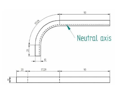
Bend allowance (BA) is the length of material along the neutral axis that is consumed by a bend during sheet metal forming. It represents the curved portion of the sheet between the two tangent points of the bend.
When a flat sheet is bent, the material on the inside of the bend is compressed while the material on the outside is stretched. The neutral axis is the transition zone between these two areas, and its position is determined by the K-factor. The bend allowance is calculated along this neutral axis.
Understanding bend allowance is important when calculating the flat pattern length of a sheet metal part. If the bend allowance is incorrect, the developed flat length may be too long or too short, resulting in inaccurate finished dimensions.
2.Bend Allowance Formula
The standard bend allowance formula is:
BA = (π / 180) × A × (R + K × T)
This formula calculates the length of material along the neutral axis that is consumed by the bend. To use it, you need four main inputs: the bend angle (A), inside bend radius (R), material thickness (T), and K-factor (K).
2.1 What Do the Variables in the Bend Allowance Formula Mean?
| Variable | Meaning |
|---|---|
| BA | Bend allowance, or the length of material along the neutral axis consumed by the bend |
| A | Bend angle in degrees |
| R | Inside bend radius |
| K | K-factor, which defines the position of the neutral axis through the material thickness |
| T | Material thickness |
2.2 Bend Allowance Formula for a 90-Degree Bend
For a 90-degree bend, the bend angle A = 90°, so the formula becomes:
BA = (π / 2) × (R + K × T)
For example, if the inside bend radius is 6 mm, the material thickness is 5 mm, and the K-factor is 0.43:
BA = (π / 2) × (6 + 0.43 × 5)
BA ≈ 12.80 mm
This means approximately 12.80 mm of material is consumed along the neutral axis by the 90-degree bend.
Bend allowance is not the same as bend deduction. If you are calculating the flat pattern using bend deduction, see our guide to Bend Deduction Formula.
3. How to Calculate Bend Allowance?
To calculate bend allowance, first determine the bend angle, inside bend radius, material thickness, and K-factor. Then enter these values into the bend allowance formula:
BA = (π / 180) × A × (R + K × T)
Follow these steps to calculate the bend allowance for a sheet metal bend.
Step 1: Determine the Bend Angle
Determine the included bend angle, A, in degrees. The bend angle is the angle through which the sheet is formed.
For example, a standard right-angle bend has a bend angle of 90°, so A = 90°.
Step 2: Determine the Inside Bend Radius
Determine the inside bend radius, R, of the formed part. The inside bend radius is measured from the center of the bend to the inside surface of the sheet metal.
Use the actual or specified inside bend radius for the material, tooling, and bending process rather than assuming that the radius is the same for every application.
Step 3: Determine the K-Factor
Select an appropriate K-factor (K) for the material, thickness, bend radius, and bending method. The K-factor represents the position of the neutral axis within the material thickness.
If the exact K-factor is not known, use a value from a reliable reference table as a starting point and validate it with an actual bend test when dimensional accuracy is important.
Step 4: Apply the Bend Allowance Formula
Once you have the bend angle, inside bend radius, material thickness, and K-factor, substitute them into the formula:
BA = (π / 180) × A × (R + K × T)
For a 90-degree bend:
BA = (π / 2) × (R + K × T)
The result is the length of material consumed by the bend along the neutral axis.
Important: Bend allowance is only one part of calculating the flat pattern. The final developed length also depends on how the straight flange dimensions are defined and whether the calculation uses bend allowance, bend deduction, or another flat-pattern method.
4. Bend Allowance Calculation Example
For example, consider a 90-degree air bend in steel with an inside bend radius of 6 mm and a material thickness of 5 mm. Because the radius is greater than the material thickness but less than three times the thickness (T < R < 3T), the appropriate row in the reference table is “Thickness to 3 × thickness.”
For a medium material in this example, the table gives a K-factor of 0.43.
Generic K-Factor Reference Table
| Generic K-factors | Aluminio | Acero | |
|---|---|---|---|
| Radius | Soft materials | Medium materials | Hard materials |
| Air bending | |||
| 0 to thickness | 0.33 | 0.38 | 0.40 |
| Thickness to 3 × thickness | 0.40 | 0.43 | 0.45 |
| Greater than 3 × thickness | 0.50 | 0.50 | 0.50 |
| Bottoming | |||
| 0 to thickness | 0.42 | 0.44 | 0.46 |
| Thickness to 3 × thickness | 0.46 | 0.47 | 0.48 |
| Greater than 3 × thickness | 0.50 | 0.50 | 0.50 |
| Coining | |||
| 0 to thickness | 0.38 | 0.41 | 0.44 |
| Thickness to 3 × thickness | 0.44 | 0.46 | 0.47 |
| Greater than 3 × thickness | 0.50 | 0.50 | 0.50 |
For this example, the bending conditions are:
Bending method: Air bending
Material: Acero
Material type: Medium
Material thickness (T): 5 mm
Inside bend radius (R): 6 mm
Radius-to-thickness ratio: R/T = 1.2
K-factor: 0.43
Because 1 < R/T < 3, the “Thickness to 3 × thickness” row applies. For medium steel under air bending, this gives a reference K-factor of 0.43.
Step 1: Calculate the Bend Allowance
Use the bend allowance formula:
BA = (π / 180) × A × (R + K × T)
Substitute the values:
BA = (π / 180) × 90 × (6 + 0.43 × 5)
First:
0.43 × 5 = 2.15 mm
Then:
BA = (π / 2) × (6 + 2.15)
BA = (π / 2) × 8.15
BA ≈ 12.80 mm
Therefore, the bend allowance is approximately 12.80 mm.
Step 2: Calculate the Flat Length
Assume the two straight sections are 20 mm y 70 mm, measured to the tangent points of the bend. The developed flat length can then be calculated as:
Flat length = L₁ + L₂ + BA
Substituting the values:
Flat length = 20 + 70 + 12.80
Flat length = 102.80 mm
Therefore, the calculated flat length is 102.80 mm.
Important: The calculation above assumes that the 20 mm and 70 mm straight lengths are measured to the bend tangent points. If the dimensions are specified as inside or outside dimensions, the flat-pattern calculation may require bend deduction or another dimensioning method instead of simply adding the bend allowance.
5. Bend Allowance and K-Factor
En K-factor directly affects the bend allowance because it determines the position of the neutral axis within the sheet thickness. The neutral axis is the layer of material that experiences approximately zero change in length during bending.
In the bend allowance formula, the K-factor is used to determine the effective radius of the neutral axis:
BA = (π / 180) × A × (R + K × T)
For the same bend angle, inside bend radius, and material thickness, a higher K-factor results in a larger calculated bend allowance. This is why selecting an appropriate K-factor is important when developing accurate flat patterns.
5.1 How Does K-Factor Affect Bend Allowance?
The K-factor represents the location of the neutral axis as a proportion of the material thickness. It is expressed as a value between 0 and 1.
For example, if the material thickness is 5 mm and the K-factor is 0.43, the neutral axis is located:
Neutral axis distance = K × T
= 0.43 × 5 = 2.15 mm
from the inside surface of the bend.
Because the neutral axis determines the effective radius used in the bend allowance calculation, changing the K-factor changes the calculated bend allowance.
5.2 How to Choose a K-Factor
There is no single K-factor that applies to every sheet metal bending application. The appropriate value depends on factors such as:
- Material type
- Material thickness
- Inside bend radius
- Bending method
- Tooling and machine setup
A K-factor reference table can provide a starting value for calculations. However, when dimensional accuracy is critical, the selected K-factor should be validated using actual material and tooling conditions.
For the most commonly used K-factor values, calculation methods, and practical examples, see our Sheet Metal K-Factor Guide.
6. Bend Allowance vs. Bend Deduction
Bend allowance and bend deduction are both used to calculate the flat pattern of a sheet metal part, but they use different dimensioning approaches. Bend allowance is the arc length of the neutral axis through the bend. Bend deduction is the amount subtracted from the combined flange dimensions to obtain the flat length.
| Item | Bend Allowance | Bend Deduction |
|---|---|---|
| What it represents | The material length consumed along the neutral axis of a bend. | The amount removed from the combined flange dimensions to obtain the flat length. |
| Typical use | Flat-pattern calculations based on straight lengths measured to the bend tangent points. | Flat-pattern calculations based on inside or outside finished dimensions. |
| Calculation inputs | Bend angle, inside radius, material thickness, and K-factor. | Finished dimensions, bend geometry, and the selected bend allowance method. |
| Key check | Confirm that the straight lengths are defined to the tangent points. | Confirm whether the drawing dimensions are inside, outside, or another reference type. |
Do not add bend allowance and bend deduction together in the same flat-pattern calculation. Select one method that matches the way the finished part is dimensioned, then validate the result using the actual material, tooling, and bending process.
For a detailed bend deduction calculation method, see our Bend Deduction Formula Guide.
7. Sheet Metal Design Considerations for Accurate Bending
7.1 Minimum Flange Length
Minimum flange length depends on material thickness, inside bend radius,V-die opening, and the way the workpiece is supported during bending. If a flange is too short, it may not be supported correctly by the die shoulders,which can lead to unstable positioning or inaccurate bend results.
Before finalizing a part design, confirm the minimum supported flange length for the selected material, tooling, and bending method. The required value should be checked against the actual V-die opening and press brake setup, rather than applying one rule to every part.
Small end flanges on large or heavy workpieces require additional attention.The workpiece may be difficult to position and support while forming a short flange, especially when manual handling is required. Where possible, review the part design, bending sequence, tooling, or handling method before releasing the flat pattern for production.
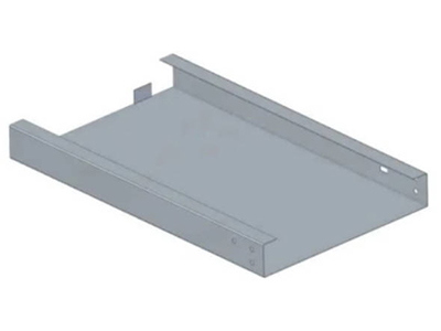
Small flange on large part:Having a small bend at the end of a large component can cause difficulties.
For large and heavy parts, it is better to omit the small flange. Because this makes manufacturing very difficult and may require manual labor. But it costs more than simple machining. Therefore, it is wiser to choose other solutions if possible.
7.2 Minimum Hole Distance from a Bend
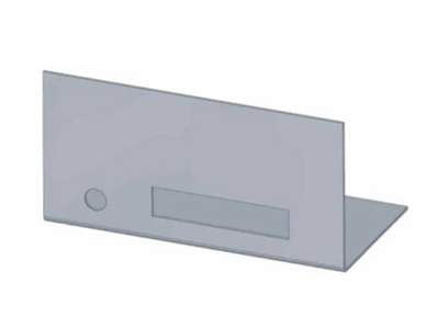
Holes located too close to a bend may deform during forming. This can affect the hole shape, dimensional accuracy, and the fit of fasteners.
When laying out holes near a bend, maintain sufficient distance between the hole edge and the bend line. The required distance depends on factors such as material thickness, bend radius, hole size, and the bending process. When dimensional accuracy is important, use the manufacturer’s or fabricator’s recommended minimum distance rather than applying one value to every material and thickness.
7.3 Bend Spacing and Adjacent Bends
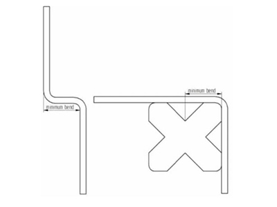
Adjacent bends require enough space for the part to be positioned and supported by the press brake tooling. If bends are placed too close together, a previously formed flange may interfere with the punch or die during a subsequent operation.
For continuous bends such as U-shaped parts, check the tooling clearance and bending sequence before finalizing the design. The distance between bends should provide enough room for the formed section to clear the tooling during each operation.
7.4 Bend Line and Part Layout
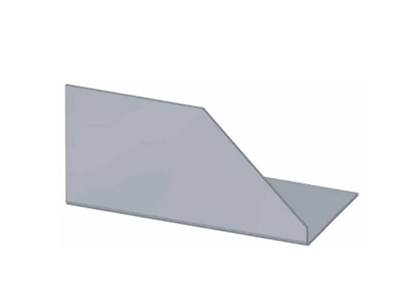
Bend-line placement affects part positioning, tooling clearance, bending sequence, and finished-part accuracy. Before releasing a flat pattern, review nearby edge features and confirm that the bend line can be referenced consistently during production.
Chamfers and Edge Features Near a Bend
A chamfer or cutout placed close to a bend can reduce the material available to form the flange and may cause edge deformation during bending. Leave sufficient material between the bend area and nearby edge features, then confirm the design against the selected tooling and minimum flange-length requirements.
Part Orientation and Symmetry
Avoid part designs that are almost symmetrical but can be loaded in more than one orientation. Clear reference features, asymmetric details, or unambiguous bend directions can help the operator identify the correct orientation and reduce the risk of producing a mirrored or incorrectly bent part.
Aligned Bend Lines
When multiple flanges share the same bend line, keeping those bends aligned can reduce repositioning and simplify the bending sequence. This may improve setup consistency, especially for repeat parts with several related bends.
Reference Edges for Positioning
A straight reference edge that remains parallel to the bend line can make material positioning and backgauge setup easier. When no reliable reference edge is available, the risk of positioning variation can increase, especially on long or repeat-production parts.
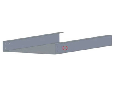
Part symmetry: Avoid designs that are almost symmetrical but can be oriented incorrectly during bending. Clear geometric differences or reference features can help the operator identify the correct orientation and bending direction, reducing the risk of producing the part incorrectly.
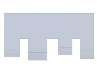
Keep bends on the same line: When multiple flanges are arranged along the same bending line, keeping the bends aligned can reduce repositioning and simplify the bending sequence. Fewer adjustments can help improve production efficiency and reduce setup time.
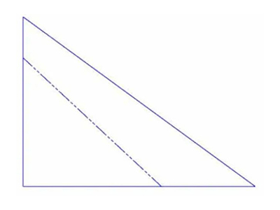
Keep the bend line parallel to a reference edge: A straight reference edge that is parallel to the bend line can make positioning and alignment easier. When the bend line is difficult to reference, accurate positioning becomes more challenging and may increase the risk of dimensional errors.
7.5 Bend Compensation and Flat Pattern
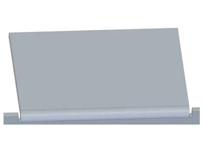
Accurate bend compensation is important when creating the flat pattern of a sheet metal part. The developed length must account for the material consumed by each bend, using bend allowance, bend deduction, or another appropriate flat-pattern calculation method.
Before cutting the sheet, verify that the flat pattern produces the required finished dimensions after bending. The calculation should account for the actual material thickness, bend radius, bend angle, and K-factor used for the application.
For more information about bend relief and how it prevents tearing or deformation near a flange, see our sheet metal bend relief guide.
7.6 Box and Tray Bending Clearance
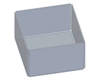
When designing a box, tray, or enclosure with multiple flanges, review the bending sequence before finalizing the flat pattern. Each completed bend changes the available clearance for the next operation, and a previously formed flange may interfere with the punch, die, backgauge, or machine frame.
Allow enough spacing between adjacent bends for the formed section to clear the tooling during each step. This is especially important for deep boxes, narrow return flanges, and parts with multiple bends close to one another.
Before production, check the flat pattern, tooling arrangement, bend sequence, and required handling position. If clearance is limited, the part may require a different bending order, segmented tooling, special punches, or a revised flange design.
7.7 Check the Flat Pattern Before Bending
Before manufacturing the part, review the flat pattern in your CAD software to verify that the developed shape can produce the required finished geometry.
Check the overall sheet size, flange dimensions, bend locations, and spacing between features. A flat-pattern review can also help identify unnecessary material usage and determine whether multiple parts can be nested efficiently on the same sheet.
Because the flat pattern depends on bend allowance, bend deduction, K-factor, and the way finished dimensions are defined, verify the calculation before sending the part for cutting.
7.8 Minimum Bend Radius
The minimum inside bend radius depends on the material, thickness, tooling, and bending method. A commonly used starting point is to use an inside bend radius around the material thickness, but this should not be treated as a universal rule.
A bend radius that is too small can increase the risk of cracking or surface damage, while a larger radius changes the geometry and affects the bend allowance calculation. Check the recommended minimum bend radius for the specific material and bending process before finalizing the design.
For material-specific guidance, see our minimum bend radius chart and guide.
7.9 Bending Direction and Material Considerations
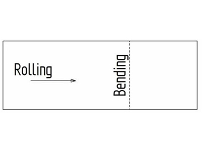
Material rolling direction can affect bend quality, particularly when working with less ductile materials, high-strength steels, or certain aluminum alloys. Depending on the material grade and forming conditions, bending in an unfavorable direction may increase the risk of cracking, surface damage, or inconsistent bend results.
When material direction is known, review the supplier’s forming recommendations before finalizing the part layout. For critical parts, validate the planned bend direction using the actual material, thickness, bend radius, tooling, and bending method.
Material properties also affect the bend allowance calculation. Strength, ductility, thickness, surface condition, and material grade can influence the required bend radius, K-factor, springback, and final bend angle.
Use material-specific production data whenever available. A generic K-factor table is useful as a starting point, but production-critical flat patterns should be verified with a test bend using the actual material and tooling conditions.
7.10 Hem and Other Special Bends
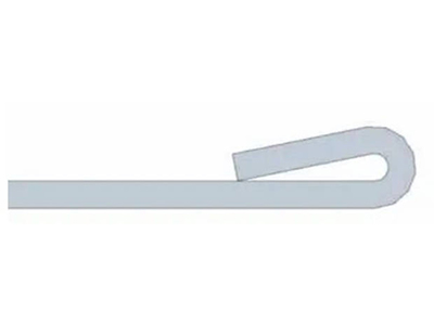
Hem bends are used to reinforce sheet metal edges, improve handling safety, and create a cleaner finished appearance. Because a hem involves additional forming after the initial bend, the material, inside radius, tooling, and forming sequence should be considered during part design.
Do not assume that every hem can be fully flattened without affecting the material. Excessive forming force may cause surface marking, cracking, or distortion, particularly in thicker materials or less ductile alloys.
Before production, confirm the required hem style, finished opening, material thickness, tooling arrangement, and bending sequence. Where dimensional accuracy or surface finish is critical, verify the process with a test bend using the actual material and tooling.
Conclusión
Accurate bend allowance calculations are essential for creating reliable sheet metal flat patterns and achieving the required finished dimensions after bending. Use the bend angle, inside bend radius, material thickness, and K-factor to calculate the material length consumed along the neutral axis.
The bend allowance formula provides a practical starting point, but the final result must match the actual material, tooling, bend radius, and bending method. When dimensional accuracy is critical, validate the selected K-factor and flat-pattern calculation with a test bend using production material.
Before releasing a part for cutting, also review flange length, bend spacing, tooling clearance, bend direction, and the bending sequence. These checks help reduce setup issues and improve repeatability during fabrication.
For production applications, accurate bend calculations should be combined with suitable press brake tooling, machine configuration, and process controls.
Durmapress CNC Press Brake machines provide precision control and automatic compensation features to help maintain consistent bending results in production.
PREGUNTAS FRECUENTES
The bend allowance formula is:
BA = (π / 180) × A × (R + K × T)
Where A is the bend angle, R is the inside bend radius, K is the K-factor, and T is the material thickness.
En K-Factor is a fundamental ratio used to determine the Bend Allowance, which quantifies the exact amount of material stretch during forming. This parameter defines the geometric relationship between the relocated centerline thickness (tt) and the initial material thickness (MTMT).
inside bend radius and a 90-degree bend angle. For this example, we'll use a K-factor of 0.446
En K-factor is the geometric ratio of the neutral axis position to the espesor del material, determining how the neutral line migrates as the sheet undergoes deformation. The specific K-factor applied is contingent upon the material properties and the bending process employed. Furthermore, this value may fluctuate significantly when there are substantial variations in material thickness.
En K-factor is influenced by a complex interplay of variables, including material type, sheet thickness, bending method, bend angle, and the inside radius. Furthermore, specific tooling geometry and mechanical properties—such as yield and tensile strength—play a significant role in its determination. In standard industrial applications, the K-factor typically ranges between 0.3 and 0.5
Quiénes somos
Durmapress se especializa en el diseño, la fabricación y la venta de diversos equipos de procesamiento de metales, como plegadoras, cizallas, punzonadoras, máquinas de corte por láser, etc. La empresa se fundó en 2000. Con años de experiencia y acumulación de tecnología. DurmaPress se ha convertido en una de las marcas más conocidas de la industria china de maquinaria para el procesamiento de metales.


Contáctenos
Entradas recientes

Categorías
Síganos
Nuevo vídeo semanal
Más información
Si tiene alguna información sobre nuestros productos, póngase en contacto con nosotros y le responderemos en 24 horas.