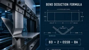
Precision in sheet metal fabrication starts with a reliable bend allowance formula and the correct K-factor. Whether you are calculating a standard 90 degree bend or complex custom angles, using an accurate sheet metal calculation formula is the only way to prevent costly material waste and production delays. This guide provides the exact bending allowance formula and K-Factor reference table you need to master your flat patterns and ensure perfect results on every press brake operation.
What is the Bend Allowance Formula?
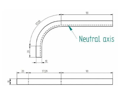
En bend allowance formula is used to determine the arc length of the neutral axis between the bend lines. For a 90 degree bend, it ensures the final part dimensions match the CAD design by accounting for material stretching.
Bend Allowance Formula
The bend allowance formula calculates the length of the neutral axis during sheet metal bending. It is used to determine the flat pattern length before bending.
BA = (π / 180) × A × (R + K × T)
Where:
BA = Bend allowance
A = Bend angle (degrees)
R = Inside bend radius
K = K-factor
T = Material thickness
For a standard 90-degree bend, set A = 90 in the formula. The calculated bend allowance is added to the straight flange lengths to determine the required flat sheet size.
Once the bend allowance is known, you can use it to calculate the bend deduction and determine the correct flat pattern length.
How to Calculate Bend Allowance?
To calculate the allowance, you must know the material thickness (t), the inside radius (ir), the bend angle (ß), and the K-Factor. Our guide below provides a step-by-step bending calculation example to simplify this process.
Bend Allowance Calculation Example
Let's say we have a bend with one straight leg of 20 mm and the other of 70 mm, a bend angle of 90°, a sheet thickness of 5 mm and an inner radius of 6 mm. We want to know the final length of the sheet. First, we have to start with the k-factor: Another way to determine the k-factor is to follow a "rule of thumb". Simply select the ak-factor from the table below according to your material. This gives sufficiently accurate results for most cases.
| Generic K-factors | Aluminio | Acero | |
|---|---|---|---|
| Radius | Soft materials | Medium materials | Hard materials |
| Air bending | |||
| 0 to thickness | 0.33 | 0.38 | 0.40 |
| Thickness to 3 × thickness | 0.40 | 0.43 | 0.45 |
| Greater than 3 × thickness | 0.50 | 0.50 | 0.50 |
| Bottoming | |||
| 0 to thickness | 0.42 | 0.44 | 0.46 |
| Thickness to 3 × thickness | 0.46 | 0.47 | 0.48 |
| Greater than 3 × thickness | 0.50 | 0.50 | 0.50 |
| Coining | |||
| 0 to thickness | 0.38 | 0.41 | 0.44 |
| Thickness to 3 × thickness | 0.44 | 0.46 | 0.47 |
| Greater than 3 × thickness | 0.50 | 0.50 | 0.50 |
Secondly, calculate the bending allowance: For the final length, we just need to add the length of the two legs to the bending allowance: L = 20 + 70 + 10 = 100mm The length of the sheet needs to be 100mm in total.
Bend Allowance and K-Factor
The arc length of the neutral axis must be used for plan view calculations.
If you make your own plan view, you need to know the following. Bending stretches the material. This means that the neutral line or axis, as we said in the springback section, is not really in the middle of the material. But the plan view must be formed following the neutral line. Finding its location requires the k factor. The k factor is an empirical constant, which means that its value is determined by testing. It varies with material, thickness, bend radius, and bending method. Basically, the k factor offsets the neutral line to provide a plan view that reflects reality. By using it, you can get the bend allowance, which is essentially the length of the neutral axis of the bend.
K factor formula:
k – k factor, constant; ir – inside radius (mm); t – sheet thickness (mm)Bend allowance formula:For bends between 0 and 90 degrees, the formula is as follows: ß – bend angle (°)For bends between 90 and 165 degrees, the formula is: For bends over 165°, it is not necessary to calculate the bend allowance, as the neutral axis remains almost in the middle of the sheet.
Sheet Metal Design Considerations Before Bending
Minimum flange length
There is a minimum flange length for sheet metal bending. Refer to the bend force table for guidance. Choose the width of the die based on the thickness. If you design the flange too short, it will awkwardly “fall” into the gap and you won’t get the results you want.
Chamfer Edge
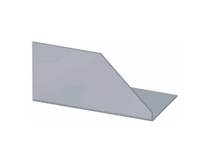
The chamfer must stop before the bottom of the detail.
If you are making a flange that is chamfered on one or both ends, the previous minimum flange length rules still apply. The chamfer must leave enough room to complete a proper bend, otherwise it will just look deformed and not really satisfying.
Bending hole distance
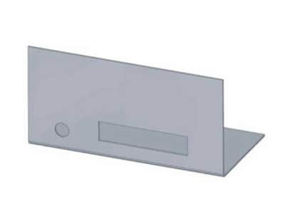
Nearby holes may warp.
If the holes are too close to the bend, they may deform. Round holes are not as problematic as other types, but your bolts may not pass smoothly through. Again, refer to the bend force table for the minimum flange measurement and place the holes farther out than the minimum.
symmetry
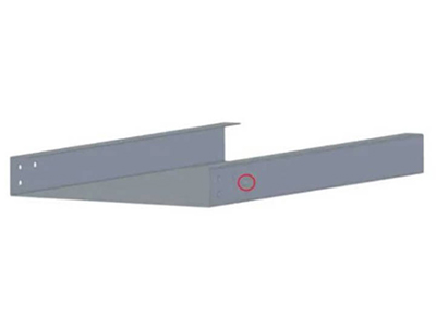
To avoid confusion, the rectangular hole can be on both sides.
There is a big risk in manufacturing almost symmetrical parts. If possible, make it symmetrical. If it is almost symmetrical, the operario de prensa plegadora may be confused. What is the result? Your part will be bent in the wrong direction. Symmetry cannot be guaranteed in every instance, but make sure it is easy to understand how it should be manufactured.
Rivet nuts
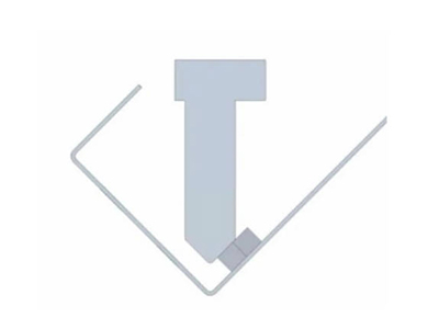
Rivet nuts block bending tools.
If rivet nuts are used near the bend line, it is known that it is helpful to insert them before bending to ensure their suitability. After bending, the hole may be deformed. Nevertheless, make sure that the nut does not hinder the tool when bending.
Small flange on large part
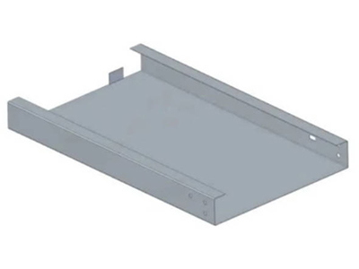
Having a small bend at the end of a large component can cause difficulties.
For large and heavy parts, it is better to omit the small flange. Because this makes manufacturing very difficult and may require manual labor. But it costs more than simple machining. Therefore, it is wiser to choose other solutions if possible.
Bend next to each other
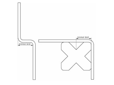
Check the bend force charts for minimum flange length.
If you want to include continuous bends, check if it is possible. Problems arise when you cannot fit the already bent part onto the die. If your bends go in the same direction - U-bends - then a general rule is to design the middle section longer than the flange.
Keep the bend in the same line
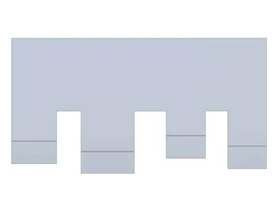
This part requires multiple adjustments.
If you have multiple flanges in a row, it is best to keep the bends in the same line. With this in mind, you can keep the number of operations to a minimum. Otherwise, the operator will need to readjust the part for each bend, which means more time and more money.
Bend line parallel to edge
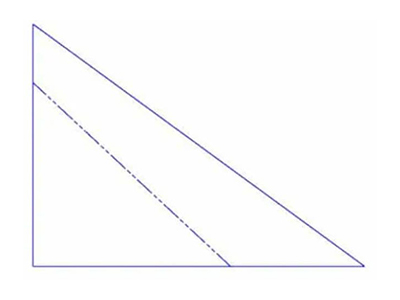
This folding line leads to inaccurate results.
For positioning, the bending line must have a parallel side. If it doesn't, aligning the part is a real headache and you may end up with unsatisfactory results.
Compensation for bending
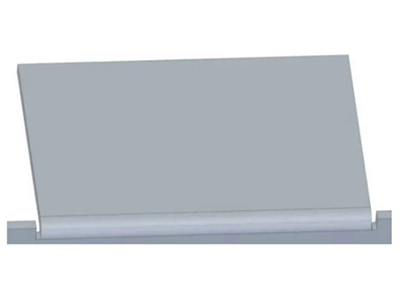
Bend relief is necessary.
For best results, it is recommended to not only make a small laser cut notch, but also make an actual cut – the bend relief – on the side of the flange to be machined. The width of this cut should be greater than the material thickness. This ensures that there is no tearing or deformation in the final bend. Another good practice is to incorporate small radii in the bend relief grooves, as they can also relieve material stress.
Bend a box
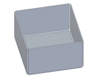
Small gaps ensure workability When bending the box, small gaps should be left between the flanges. Otherwise, the final bend will hit the existing bend, thus destroying the entire structure.
Check the Flat Pattern
One thing to remember is to switch your CAD view to the flat pattern from time to time. There are many benefits to doing this. Firstly, if you are limited by your flange, you may end up with something that cannot exist in the flat pattern. What cannot exist in the flat pattern, cannot exist any other way. Measure the layout. Perhaps you can adjust the design to achieve the best fit. Try to avoid using a larger sheet if the smaller size can be achieved. Perhaps you can fit two pieces on the same sheet if you just subtract a few millimeters? This will be reflected in the final quote. It plays a big role in getting a good result.
Rules of thumb for minimum bend radius
Keep things simple. What could be simpler than choosing an inside radius (ir) that is the same as the material thickness. This avoids headaches, overthinking and silly mistakes later on. Going below that value may cause you problems. A larger radius will just make some other calculations more difficult.
Bending direction
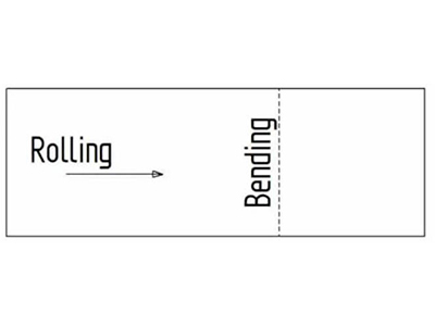
Bends perpendicular to the roll.
You should not design your bends in the same direction that the material is rolled. This is particularly important with aluminium and Hardox steel. Of course, we all know that aluminium housings have 4 sides, which means the bending operation is the opposite of what we recommend. Still, avoid it if possible. The result can be an uneven surface or even cracking. While the manufacturing engineer will notice these things, it is good to notice them yourself. It helps to illustrate the use of the material.
Hem
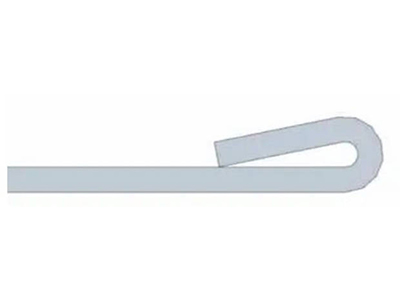
Leave an inside radius if possible.
If you want to strengthen the edge of your sheet metal, a hem is a good option. However, the other recommendations still apply. It is best to leave a small radius inside the hem. It would take a lot of force and tonnage to completely crush the radius. In addition, it would put the material at risk of cracking. Leaving a radius, on the other hand, mitigates this risk.
Consider Materials
Regular 1-3mm thin structural steel plates will take on just about anything. After that, you need to do your research. Some materials are much more willful in the way they are handled. Getting a good result depends on your knowledge and the help your production engineers can provide.
Conclusión
Mastering bend allowance calculations and the K-factor is more than just a theoretical exercise—it is a fundamental requirement for high-quality sheet metal fabrication. By accurately predicting material stretching, engineers can eliminate the trial-and-error process, drastically reduce material waste, and ensure that flat patterns translate perfectly into finished components.
Whether you are designing a simple bracket or a complex enclosure, remember that consistency is key. Always use the appropriate bending allowance formula for your specific angle, refer to reliable K-factor charts, and orient your bends across the material grain whenever possible.
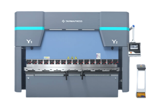
For precision-critical projects, having the right calculations is only half the battle; you also need high-performance equipment. Durmapress CNC Press Brake machines are designed to work seamlessly with these engineering parameters, offering automatic compensation and precision control to help you achieve the perfect bend every time.
PREGUNTAS FRECUENTES
En K-factor is defined as the ratio of the neutral axis offset (tt) to the overall espesor del material (MtMt), expressed by the formula: K-factor=t/MtK-factor=t/Mt. Functioning as a mathematical multiplier, it determines the precise position of the relocated neutral axis during bending. Due to their mathematical interdependence, the K-factor can also be accurately derived if the bend allowance is already known.
En K-Factor is a fundamental ratio used to determine the Bend Allowance, which quantifies the exact amount of material stretch during forming. This parameter defines the geometric relationship between the relocated centerline thickness (tt) and the initial material thickness (MTMT).
inside bend radius and a 90-degree bend angle. For this example, we'll use a K-factor of 0.446
En K-factor is the geometric ratio of the neutral axis position to the espesor del material, determining how the neutral line migrates as the sheet undergoes deformation. The specific K-factor applied is contingent upon the material properties and the bending process employed. Furthermore, this value may fluctuate significantly when there are substantial variations in material thickness.
En K-factor is influenced by a complex interplay of variables, including material type, sheet thickness, bending method, bend angle, and the inside radius. Furthermore, specific tooling geometry and mechanical properties—such as yield and tensile strength—play a significant role in its determination. In standard industrial applications, the K-factor typically ranges between 0.3 and 0.5
For example, let's say one user sends five referral invites. If 20% convert, the k-factor equation gives you 1.0. At that point, each user refers an additional user. Even small lifts in conversion rate can lead to a higher K-factor and more efficient user acquisition.
Quiénes somos
Durmapress se especializa en el diseño, la fabricación y la venta de diversos equipos de procesamiento de metales, como plegadoras, cizallas, punzonadoras, máquinas de corte por láser, etc. La empresa se fundó en 2000. Con años de experiencia y acumulación de tecnología. DurmaPress se ha convertido en una de las marcas más conocidas de la industria china de maquinaria para el procesamiento de metales.


Póngase en contacto con nosotros
Entradas recientes

Categorías
Síguenos
Nuevo vídeo semanal
Más información
Si tiene alguna información sobre nuestros productos, póngase en contacto con nosotros y le responderemos en 24 horas.