



About Us
Learn press brake bending radius with charts, formulas, and expert tips. Avoid cracking, improve accuracy, and optimize sheet metal bending.




Contact Us
Recent Posts



Categories
Follow Us
Weekly New Video
Quick answer:
In press brake air bending, the inside bend radius is mainly controlled by the V-die opening, material thickness, material type, and tensile strength. For mild steel, a common estimate is:
Inside Bend Radius ≈ 0.16 × V-die opening
For stainless steel, the inside radius is often closer to 0.20–0.22 × V-die opening because of higher tensile strength and springback.
Use the bend radius chart and V-die opening chart below as starting references, then confirm the final radius with a test bend.
1. Introduction
In sheet metal fabrication, achieving precise and consistent bends is critical for product quality and production efficiency. One of the most important yet often misunderstood parameters is the press brake bending radius.
Whether you are an engineer designing parts, a fabricator operating a press brake, or a buyer selecting equipment, understanding bending radius helps you:
- Prevent material cracking
- Improve dimensional accuracy
- Optimize tooling and machine selection
This guide provides a complete overview of bending radius, including standard charts, calculation formulas, and practical selection tips used in real-world manufacturing.
2. What Is Bending Radius in Press Brake?
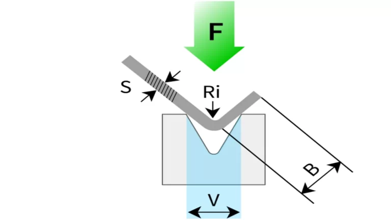
The bending radius refers to the inside radius (IR) formed when sheet metal is bent using a press brake.
- Inside Radius (IR): Radius on the inner side of the bend
- Outside Radius: Outer curve after bending
- Neutral Axis: The layer in the material that neither compresses nor stretches
In most press brake applications, the inside radius is the key reference for calculations and tooling selection.
3. Why Bending Radius Matters
Choosing the correct bending radius is essential for both product quality and manufacturing efficiency.
1. Prevents Material Cracking
If the radius is too small relative to material thickness, the outer fibers stretch excessively and may crack—especially in stainless steel or high-strength materials.
2. Ensures Dimensional Accuracy
Incorrect radius leads to errors in bend allowance and final part dimensions, affecting assembly fit.
3. Affects Springback
Larger bending radii typically result in greater springback, requiring compensation during bending.

4. Press Brake Bend Radius Chart by Material and Thickness
The following press brake bend radius chart provides typical minimum inside radius recommendations for common sheet metals. These values are general starting points for air bending. Actual results may vary depending on material grade, temper, tensile strength, grain direction, tooling selection, V-die opening, and bending method.
| Material | Sheet Thickness | Recommended Minimum Inside Radius | Typical V-Die Opening |
|---|---|---|---|
| Mild Steel | 1 mm | 1 mm | 8 mm |
| Mild Steel | 2 mm | 2 mm | 16 mm |
| Mild Steel | 3 mm | 3 mm | 24 mm |
| Mild Steel | 4 mm | 4 mm | 32 mm |
| Mild Steel | 6 mm | 6–8 mm | 48 mm |
| Stainless Steel | 1 mm | 1.5–2 mm | 10 mm |
| Stainless Steel | 2 mm | 3–4 mm | 20 mm |
| Stainless Steel | 3 mm | 4.5–6 mm | 30 mm |
| Stainless Steel | 4 mm | 6–8 mm | 40 mm |
| Aluminum | 1 mm | 1–1.5 mm | 10–12 mm |
| Aluminum | 2 mm | 2–3 mm | 20–24 mm |
| Aluminum | 3 mm | 3–4.5 mm | 30–36 mm |
| Aluminum | 4 mm | 4–6 mm | 40–48 mm |
Minimum bending radius is usually expressed as a multiple of material thickness (T).
Mild steel: recommended minimum inside radius ≈ 1T
Stainless steel: recommended minimum inside radius ≈ 1.5T–2T
Aluminum: recommended minimum inside radius ≈ 1T–1.5T, depending on alloy and temper
Press Brake V-Die Opening vs Bend Radius Chart
In air bending, the inside bend radius is closely related to the V-die opening. A larger V opening usually produces a larger inside radius and lower bending force, while a smaller V opening produces a tighter radius but increases the risk of cracking, surface marking, and excessive tonnage.
For mild steel, a common estimate is:
Inside Radius ≈ 0.16 × V-opening
For stainless steel, the inside radius is often closer to:
Inside Radius ≈ 0.20–0.22 × V-opening
| Material | Common V-Die Opening Rule | Approximate Inside Radius in Air Bending |
|---|---|---|
| Mild steel | 8 × T | 0.16 × V |
| Stainless steel | 10 × T | 0.20–0.22 × V |
| Aluminum | 10–12 × T | Depends on alloy and temper; wider V reduces cracking and marking |
Example:
If bending 2 mm mild steel with a 16 mm V-die opening:
Inside Radius ≈ 0.16 × 16 = 2.56 mm
This estimated value should be used as a starting point. The actual inside radius must be confirmed with a test bend because material strength, grain direction, punch radius, and tool wear can change the result.
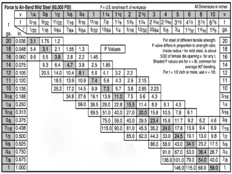
Reference: Air-Bending Force Chart for Mild Steel
The chart below is an example of an air-bending force chart for mild steel. It shows the relationship between material thickness, V-die opening, approximate inside radius, and required bending force. Because this chart uses inch units and mild steel data, it should be used only as a reference example. For metric bend radius selection, use the bend radius and V-die opening tables above.

5. Bending Radius Calculation Formula
Understanding formulas helps improve precision and reduce trial-and-error.
5.1 Inside Radius Estimation (Air Bending)
For air bending, the inside radius is usually estimated from the V-die opening rather than from the punch radius alone. A widely used empirical formula for mild steel is:
R ≈ V / 6
or:
R ≈ 0.16 × V
Where:
R = estimated inside bend radius
V = V-die opening width
Example:
For a 3 mm mild steel sheet using a 24 mm V-die opening:
R ≈ 24 / 6
R ≈ 4 mm
The expected inside bend radius is approximately 4 mm.
This formula is a starting estimate for air bending. Stainless steel often forms a larger inside radius because of higher tensile strength and springback. In that case, the radius may be closer to 0.20–0.22 × V, depending on material grade, tooling condition, and bending method.
5.2 Bend Allowance Formula
To calculate flat pattern length:
BA = (π × (R + K × T) × A) / 180
Where:
- BA = Bend Allowance
- R = Inside radius
- T = Material thickness
- K = K-factor (typically 0.3–0.5)
- A = Bend angle (degrees)
5.3 K-Factor Reference
| Material | Typical K-Factor |
|---|---|
| Mild Steel | 0.3 – 0.4 |
| Stainless Steel | 0.4 – 0.5 |
| Aluminum | 0.33 – 0.4 |
5.4 Springback Estimation (Conceptual)
Springback depends on material properties:
Springback ∝ (Yield Strength / Elastic Modulus)
👉 Stronger materials = more springback
6. Factors Affecting Bending Radius
Several variables influence the final bending radius:
1. Material Type
- Stainless steel → larger radius required
- Aluminum → more flexible but varies by temper
2. Material Thickness
Thicker sheets require larger radii to avoid cracking.
3. Tooling (Die Opening)
Larger V-opening → larger bending radius
4. Bending Method
Different methods produce different radius behavior.
5. Grain Direction
Bending across the grain reduces cracking risk compared to bending along the grain.
7. Bending Methods vs Radius
Different press brake bending methods affect radius control and accuracy.
| Method | Radius Control | Accuracy | Force Required |
|---|---|---|---|
| Air Bending | Flexible | Medium | Low |
| Bottoming | More fixed | High | Medium |
| Coining | Very precise | Very High | Very High |
Key Insight:
- Air bending: Most common, flexible radius control
- Coining: Best precision but highest tonnage requirement
8. Common Bending Radius Mistakes
Avoiding these mistakes can significantly reduce production issues:
❌ Radius Too Small
Leads to cracking or surface defects
❌ Ignoring Springback
Results in inaccurate bend angles
❌ Wrong Tool Selection
Incorrect die opening leads to inconsistent radius
❌ Ignoring Grain Direction
Increases risk of fracture
❌ No Test Bending
Skipping trial bends leads to costly errors in batch production
👉 Choosing the right press brake and tooling setup can effectively eliminate most of these problems.
9. How to Choose the Right Press Brake Bend Radius
A practical step-by-step approach:
Step 1: Identify Material & Thickness
Start with material specs and mechanical properties
Step 2: Refer to Standard Chart
Use recommended minimum radius values
Step 3: Select the Correct V-Die Opening for the Required Bend Radius
Apply rule:
V ≈ 6T – 10T (depending on material)
For most air bending applications, the V-die opening is usually selected based on material thickness. A wider opening reduces forming force but increases the inside bend radius.
Step 4: Estimate Radius
Use:
R ≈ V / 6
Step 5: Compensate for Springback
Adjust angle or tooling
Step 6: Perform Test Bending
Validate before mass production
💡 Practical Tip:
Modern CNC press brakes (such as DURMAPRESS systems) can automatically compensate for bending parameters, improving consistency and reducing setup time.
10. FAQ
Q1: What is the minimum bend radius for sheet metal?
It depends on material and thickness, typically ranging from 1T to 2T.
Q2: How do you calculate bending radius?
Use the empirical formula:
R ≈ V / 6
Or refer to standard bending charts.
Q3: Why does metal crack during bending?
Common causes include:
- Radius too small
- Incorrect grain direction
- Material too hard
Q4: Does bending method affect radius?
Yes. Air bending allows flexible radius control, while coining produces a fixed radius.
Q5: What is a good K-factor value?
Typically between 0.3 and 0.5, depending on material type.
Q6: What is the standard bend radius for a press brake?
The standard bend radius depends on material type, thickness, and tooling selection. In many air bending applications, the inside radius is approximately 1T for mild steel and 1.5T-2T for stainless steel. However, the actual radius should be confirmed using a press brake bend radius chart and V-die opening selection.
Q7: How does V-die opening affect press brake bend radius?
The V-die opening has a direct effect on the inside bend radius during air bending. A larger V-opening produces a larger bend radius, while a smaller opening creates a tighter radius. The relationship can be estimated using R ≈ V/6.
Q8:What is the press brake bend radius formula?
For air bending mild steel, a common estimate is: Inside Radius ≈ 0.16 × V-die opening. For example, a 16 mm V-die opening produces an estimated inside radius of about 2.56 mm. Stainless steel may form a larger radius, often around 0.20–0.22 × V-opening, depending on tensile strength and springback.
Q9:What V-die opening should I use for air bending?
A common starting rule is 8 × material thickness for mild steel, 10 × material thickness for stainless steel, and 10–12 × material thickness for aluminum. The final selection should also consider required inside radius, bend angle, material tensile strength, and surface marking risk.
Conclusion
Understanding and controlling the press brake bending radius is essential for achieving high-quality sheet metal parts. By combining standard charts, calculation formulas, and proper tooling selection, manufacturers can:
- Reduce defects
- Improve efficiency
- Ensure consistent results
For high-precision applications, investing in advanced press brake systems and proper tooling is equally important.