

Sobre nós
Durmapress specializes in designing, manufacturing, and selling various metal processing equipment, including bending machines, shears, punches, and laser cutting machines. The company was founded in 2014, with years of experience and technology accumulation. DurmaPress has become one of the well-known brands in China's metal processing machinery industry.




Contate-nos
Publicações recentes



Categorias
Siga-nos
Novo vídeo semanal
Table of Contents
A CNC press brake is built from a set of interconnected systems. Each part has a defined role — and when any one of them is misaligned, worn, or incorrectly configured, the result shows up immediately in the finished bend.
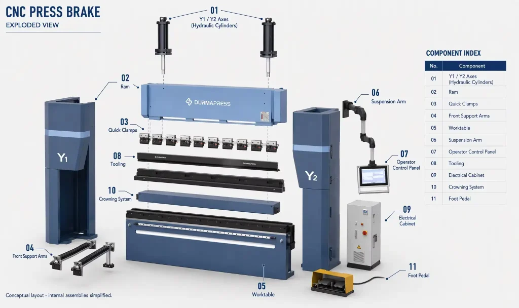
This guide covers the complete CNC press brake parts and structure: what each component is, where it sits on the machine, what it does, and how it interacts with the rest of the system. A labeled structure diagram is included as the primary visual reference, followed by a component-by-component breakdown.
1. CNC Press Brake Structure Diagram

1.1 CNC Press Brake Parts at a Glance
The diagram above identifies 11 primary components. The table below maps each one to its function and its role in bending accuracy. Components are grouped into three functional categories: structural, motion and power, and control and positioning.
| No. | Component | Category | Primary Function | Relevance to Bending Accuracy |
|---|---|---|---|---|
| 01 | Y1 / Y2 Hydraulic Cylinders | Motion & Power | Drive the ram downward on both sides | High — synchronization determines left-to-right angle consistency |
| 02 | Ram (Upper Beam) | Structural | Carries the punch; transmits bending force | High — parallelism across the stroke determines angular uniformity |
| 03 | Quick Clamps | Control & Positioning | Secure the upper tooling to the ram | Medium — affects tooling alignment and changeover speed |
| 04 | Front Support Arms | Control & Positioning | Support the sheet during positioning and bending | Medium — reduces sheet sag and positioning error on large workpieces |
| 05 | Worktable (Bed) | Structural | Supports the die, workpiece, and crowning system | High — deflection under load affects long-bend angle uniformity |
| 06 | Suspension Arm | Structural | Mounts the operator control panel | Low direct — affects operator ergonomics and programming access |
| 07 | Operator Control Panel | Control & Positioning | CNC programming and machine monitoring interface | High — coordinates all axes and compensation settings |
| 08 | Tooling (Punch & Die) | Motion & Power | Shapes the workpiece during the bend | High — tooling geometry and condition define bend angle and radius |
| 09 | Electrical Cabinet | Motion & Power | Houses drives, wiring, protection, and control hardware | Indirect — affects system reliability and serviceability |
| 10 | Sistema de coroação | Control & Positioning | Compensates for ram and bed deflection on long bends | High for long workpieces — corrects open-center angle errors |
| 11 | Pedal | Control & Positioning | Activates the bending cycle hands-free | Low direct; high safety relevance |
Note: The backgauge assembly and linear scales are not visible in the exploded-view diagram; they are covered in detail in the relevant sections below.
2. Main Components of a CNC Press Brake
The sections below follow the same numbering as the structure diagram. Where components form a logical system — such as the hydraulic circuit or the CNC feedback loop — they are explained together.
2.1 Frame, Side Housings, Ram, and Bed
These four components form the load-bearing skeleton of the machine. They do not move during bending, but they carry the full bending force and determine how the machine behaves under load.
Frame and side housings
The frame consists of two heavy side housings welded to a base and upper cross-beam. It supports every other component on the machine and guides the ram's vertical travel. When the hydraulic cylinders apply downward force, the reaction pulls the tops of the side housings outward. On a C-frame machine, this creates a controlled and predictable opening at the throat — engineered into the design, but significant if frame steel is too thin or construction quality is poor.
Frame quality indicators worth checking when evaluating a machine:
- Steel plate grade and wall thickness used in the side housings
- Whether stress-relief heat treatment is applied after welding
- Precision machining of the ram guide surfaces
- Overall machine weight relative to rated tonnage — more steel generally means a more rigid structure
Ram (Upper Beam) — Component 02
The ram carries the upper punch and transmits bending force to the workpiece. Its most important requirement is parallelism: it must remain parallel to the bed throughout the stroke, including under eccentric or off-center loading.
Ram guidance is provided by precision-machined surfaces along the side housings — commonly called gibs or slideways. As clearance between the ram and its guides increases with wear, the ram can tilt under load, producing a tapered angle across the workpiece length.
Bed / Worktable — Component 05
The bed is the stationary lower platform that supports the die, workpiece, and crowning system. It must remain flat and properly aligned with the ram under working load. On long bends with heavy material, the center of the bed bows downward as the tooling resists applied force. The crowning system compensates for this — but only if it is present and correctly calibrated for the job.
2.2 Y1/Y2 Hydraulic Cylinders and Hydraulic System — Component 01
The two hydraulic cylinders — Y1 on the left, Y2 on the right — are mounted at the top of the side housings and drive the ram downward. In a CNC electro-hydraulic press brake, each cylinder is independently controlled by a proportional valve and continuously monitored by a linear scale.
The core challenge is synchronization. When a short part is positioned on the left side of the bed, Y1 carries the full bending load while Y2 runs nearly unloaded. Without active control, the unloaded cylinder descends faster. The CNC detects this imbalance through the linear scales and adjusts each proportional valve independently to keep both sides moving in parallel.
Supporting hydraulic components:
- Hydraulic pump: Converts motor rotation into pressurized fluid flow. Variable-displacement piston pumps are common on CNC press brakes because they match output to demand, reducing heat generation during non-forming strokes.
- Proportional valves: Regulate direction, pressure, and flow to each cylinder; enable independent micro-corrections during the bending stroke.
- Hydraulic oil tank: Reservoir that also helps dissipate heat from the system.
- Filters: Remove metal particles and contaminants. Contaminated oil is a leading cause of valve response degradation and cylinder seal wear.
- Pressure relief valves: Protect the system from overload by diverting excess pressure.
- Cooler / heat exchanger: Maintains oil temperature within the operating range. Oil viscosity changes with temperature, which affects valve response and synchronization stability if left uncontrolled.
Buyer consideration: Confirm that the machine uses independent electro-hydraulic servo control on both Y1 and Y2 — not a mechanical torsion bar or a simple flow divider. Independent servo control with closed-loop feedback is the basis for consistent angle accuracy across varying load positions.
2.3 CNC Controller, Linear Scales, and Closed-Loop Feedback — Component 07
CNC controller and operator control panel
The CNC controller coordinates every axis on the machine. The operator enters material type, thickness, bend angle, flange length, tooling data, and bend sequence. The system calculates the required ram depth, backgauge position, crowning value, and approach speed for each operation.
Modern CNC systems used on electro-hydraulic press brakes typically offer:
- Multi-axis backgauge control (X, R, Z as standard; additional axes available)
- Graphical bend simulation with collision checking before production
- Stored program libraries for recurring parts
- Automatic springback compensation input
- Diagnostic display for axis positions, pressures, and service alerts
The control panel is mounted on the suspension arm (Component 06) so the operator can reposition it for programming, setup, and in-process checks.
One practical limitation: the CNC can only compensate within the machine's physical capabilities. A control system cannot correct for a warped frame, worn ram guides, or a crowning system that is out of calibration. It manages predictable, measurable variation — not mechanical conditions that fall outside its model.
Linear scales and closed-loop feedback
Linear scales are high-precision position sensors mounted on both sides of the machine, measuring actual Y1 and Y2 ram positions directly. The CNC reads these sensors continuously during the bending stroke and adjusts the proportional valves to correct any developing imbalance between the two sides.
This closed-loop arrangement is what separates a CNC electro-hydraulic press brake from an open-loop NC machine. Without it, angle accuracy degrades progressively as tooling wears, hydraulic oil heats up, or material properties vary across a production run.
Maintenance note: Linear scale strips and reader heads must be kept clean. In a fabrication environment, oil mist, grinding dust, and metal fines settle on exposed scale surfaces. A contaminated scale can drop position readings, causing the CNC to misinterpret actual ram location and overcompensate — producing unexplained angle variation that may initially appear to be a hydraulic or programming problem.
2.4 Tooling (Punch and Die) and Quick Clamps — Components 08 and 03
Punch and die — Component 08
The punch mounts on the ram; the die installs on the bed. Together, they define the bend angle, inside radius, and minimum achievable flange length.
Tooling selection depends on:
- Material type and thickness
- Required inside bend radius
- Flange geometry — short flanges, deep boxes, and offset bends each require specific profiles
- Bending method: air bending, bottoming, or coining
Common tooling types:
| Tooling | Typical Application |
|---|---|
| Standard V-die | Most air bending operations; versatile across material thicknesses |
| Gooseneck punch | Deep-flange and box bending where vertical clearance is limited |
| Radius punch/die | Parts requiring a curved profile rather than a sharp inside radius |
| Hemming tool | Folding edges onto themselves for clean, burr-free sheet edges |
| Offset die | Creating Z-bend profiles in a single stroke |
| Custom tooling | Specialized geometries not achievable with standard profiles |
Tooling condition directly affects bend angle accuracy. A punch tip that has flattened from overtonnaging, or a die shoulder that has been coined, changes the effective bending geometry. Worn tooling produces quality problems that are easily misattributed to machine settings or CNC parameters.
Quick clamps — Component 03
The quick-clamp system secures the upper tooling to the ram. Manual lever clamps are the most common configuration on standard machines; hydraulic and pneumatic automatic clamping is available for higher changeover frequency environments.
Clamping security affects tooling alignment. If tooling shifts longitudinally along the ram during bending — a risk with worn manual clamps or improper seating — the punch centerline moves relative to the die, producing angular or dimensional inconsistency that is difficult to trace back to its cause.
2.5 Crowning System — Component 10
When the ram descends under load, its center bows slightly upward because the hydraulic cylinders apply force only at the two ends. At the same time, the bed bows downward under the reaction force from the tooling. These two opposing curves widen the tool gap at the center of the machine — causing the center of a long workpiece to receive less punch penetration than the ends, and to bend to a more open angle.
The crowning system applies a controlled upward force at the center of the bed to pre-compensate for this deflection.
Two main types are used in production machines:
Mechanical (wedge) crowning
- Precision-machined steel wedges beneath the bed, adjusted by a motor
- Rigid and temperature-stable — does not drift with hydraulic oil temperature changes
- Suited to shops bending similar materials and thicknesses consistently
- Requires recalibration when switching between significantly different job parameters
Hydraulic CNC crowning
- An array of small hydraulic cylinders beneath the bed, controlled automatically by the CNC
- Adjusts compensation value with each new bending program based on material, tonnage, and bend length
- More suitable for job shops running varied materials and thicknesses
The degree of correction a crowning system provides depends on the machine model, the bend length, the material being bent, and the applied tonnage. Deflection behavior varies — there is no single value that applies across all configurations. If you are experiencing open-center angle errors on long bends, crowning calibration is the first place to check before adjusting tonnage or CNC depth parameters.
2.6 Backgauge and Front Support Arms — Components 04 and Backgauge Assembly
Calibre traseiro
The crowning system and hydraulic cylinders control bend angle. The backgauge controls flange dimension. These are distinct functions — both must be accurate for a finished part to meet its drawing.
The backgauge is a motorized stop system mounted behind the die. The operator or CNC positions it at the required distance from the tooling centerline. The operator slides the sheet against the gauge fingers, and the punch descends at the correct location for the programmed flange length.
On CNC press brakes, the backgauge moves along multiple servo-driven axes:
- X axis: Front-to-back movement — sets flange length
- R axis: Vertical movement of the gauge beam — adjusts finger height for different tooling heights and part geometries
- Z axis: Lateral finger spacing — positions fingers to avoid contact with existing bends or part features
A 3-axis (X, R, Z) backgauge handles most production bending. Parts with varying flange lengths, conical bends, or complex multi-bend profiles may require additional axes. The appropriate axis count depends on your part range — it is not necessary to over-specify for jobs that a 3-axis configuration handles reliably.
Note: Gauge finger accuracy is cumulative. Worn or misaligned finger tips introduce dimensional variation that exceeds the axis drive's positioning specification. Inspect gauge fingers regularly — they are consumable items.
Front support arms — Component 04
Front support arms are adjustable brackets on rails along the front of the bed. They support the sheet during positioning, preventing the weight of unsupported material from pulling the sheet away from the backgauge before the punch contacts it.
On thin, large-format sheets, a sheet that sags slightly under its own weight before bending can shift enough at the gauge contact point to produce flange variation that looks like a backgauge or program error. Front support arms eliminate this variable.
2.7 Electrical Cabinet and Safety Devices — Component 09 and Component 11
Electrical cabinet — Component 09
The electrical cabinet houses the drives, relays, circuit breakers, PLC, wiring, and connection terminals that power and protect the entire machine. On a well-built press brake, the cabinet has organized cable management, proper cooling, clear labeling, and good access for service.
The drives control the servo motors powering the backgauge axes. The main hydraulic motor is typically started through a variable-frequency drive (VFD), which reduces startup current and allows the pump speed to be matched to demand during light-duty strokes.
Cabinet layout and build quality are a reliable indicator of overall machine engineering. A disorganized cabinet with bundled wiring, unlabeled terminals, or inadequate cooling is worth noting during machine evaluation.
Foot pedal and safety devices — Component 11
The foot pedal activates the bending cycle, allowing the operator to keep both hands on the sheet during positioning. Most configurations offer a staged action — light pressure brings the ram to a defined safe position above the tooling, and full pressure completes the bending stroke.
Standard safety features on a CNC press brake:
- Laser safety system (AOPD): Projects a beam just above the tooling zone; the ram stops when the beam is interrupted. Actual stop behavior depends on the specific safety system, operating mode, and machine configuration — refer to the machine manual for the safety performance data applicable to your model.
- Emergency stop buttons: Located on the control panel and at the machine perimeter
- Light curtains: Infrared guarding that halts the machine when the protected zone is entered
- Guard fences: Physical barriers preventing access to non-guarded areas during operation
For safety compliance requirements applicable to your region, refer to the Durmapress machine manual and the relevant regional directives or standards.
3. How CNC Press Brake Components Work Together

A single bending cycle draws on every system described above. Here is how they interact in sequence:
- Program loaded: The CNC retrieves the stored bending program — material, thickness, tooling, bend angle, flange length, and bend sequence are all defined.
- Backgauge positions: The X, R, and Z axes move to the first programmed position. The crowning system pre-loads for the expected deflection at the current bend length and tonnage, if applicable.
- Operator loads material: The sheet rests on the front support arms and is pressed against the gauge fingers.
- Foot pedal activated: The ram descends at fast-approach speed toward the safety position above the tooling.
- Bending stroke begins: Y1 and Y2 cylinders apply force. Linear scales monitor both sides continuously; the CNC adjusts the proportional valves to maintain ram parallelism.
- Target depth reached: The CNC confirms the programmed ram depth on both axes and stops the stroke.
- Ram retracts: The cylinders reverse and the ram returns to home position.
- Backgauge repositions: For multi-bend parts, the backgauge automatically moves to the next position and the sequence repeats.
The accuracy of the finished part depends on all eight steps working correctly. An error in any one — contaminated linear scales, a worn gauge finger, an uncalibrated crowning value — will affect the result in a way that is specific and traceable.
4. Common Press Brake Bending Problems and Their Causes
The table below summarizes the three most common quality problems related to press brake parts and structure, with first-check priorities for each.
| Symptom | Likely Cause | First Checks |
|---|---|---|
| Angle correct at ends, open in the center of a long bend | Insufficient crowning; ram or bed deflection not compensated |
|
| Different angles on the left and right sides | Y1/Y2 synchronization error; linear scale contamination or offset; ram-guide wear |
|
| Inconsistent flange lengths from the same program | Gauge finger wear or misalignment; X-axis mechanical play; inconsistent operator technique |
|
For operations involving linear scale calibration, hydraulic system adjustments, or ram guide clearance measurement, consult the Durmapress machine manual or contact a qualified service technician.
5. What to Check When Buying a CNC Press Brake
Tonnage rating is the first specification most buyers look at — and one of the least useful on its own. A machine's ability to deliver consistent angle accuracy over its working life depends far more on frame construction, ram guidance, synchronization system, and deflection compensation than on the number printed on the data plate.
Structural and accuracy checklist:
| Evaluation Area | What to Ask |
|---|---|
| Frame construction | Steel grade and plate thickness? Stress-relief treatment after welding? Precision machining of ram guide surfaces? |
| Ram guidance | Design clearance between ram and gibs? How is this maintained over machine life? |
| Y1/Y2 synchronization | Independent electro-hydraulic servo control on both sides? Linear scales fitted on both axes? |
| Coroação | Included as standard or optional? Mechanical or CNC hydraulic? Does it adjust automatically per program? |
| Accuracy verification | What factory tests are performed? Under what conditions? What documentation is provided at delivery? |
| Peso da máquina | Gross machine weight relative to rated tonnage — a useful proxy for frame steel content |
Configuration questions based on your production:
Before specifying axis count, clamping type, or support equipment, define:
- What is the maximum bending length and material thickness in your regular production?
- What angle tolerance does your end product require across that length?
- How frequently do you change tooling, and how many different part programs do you run per shift?
- Do your parts include tapered flanges, multiple bends, or offset profiles that require additional backgauge axes?
- Will you regularly bend large-format or heavy sheets that need support equipment?
Answers to these questions determine whether CNC crowning is necessary, which backgauge axis count is appropriate, and whether front support or follower equipment adds genuine value for your work.
For a detailed comparison of Durmapress CNC press brake models by bending length, tonnage, and standard configuration, visit the Prensa dobradeira CNC product range.
6.FAQ
Q1: What are the main parts of a CNC press brake?
Answer: The primary components are the frame, side housings, ram, bed, Y1/Y2 hydraulic cylinders, punch and die tooling, quick clamps, crowning system, backgauge, linear scales, CNC controller, electrical cabinet, and foot pedal. Each affects a different aspect of machine performance — structural components carry the bending load, while the control and positioning components determine accuracy and repeatability.
Q2: What does the crowning system do on a press brake?
Answer: Under bending load, both the ram and bed deflect — the ram bows upward at the center, and the bed bows downward. Without compensation, this widens the tool gap at mid-span and causes the center of a long workpiece to bend to a more open angle than the ends. The crowning system applies a controlled upward force at the center of the bed to pre-compensate for this deflection. Mechanical crowning uses adjustable wedges; CNC hydraulic crowning adjusts automatically based on the programmed tonnage, bend length, and material.
Q3: What is the difference between Y1 and Y2 on a press brake?
Answer: Y1 and Y2 designate the left and right hydraulic cylinders that drive the ram. In a CNC electro-hydraulic press brake, each is controlled independently by its own proportional valve and monitored by a linear scale. The CNC synchronizes their movement continuously throughout the bending stroke — particularly important when bending a workpiece positioned off-center, where one cylinder carries significantly more load than the other.
Q4: How does a press brake backgauge work?
Answer: The backgauge is a motorized stop system mounted behind the die. It positions the sheet at the correct distance from the tooling centerline before each bend, which determines the flange length. On a CNC press brake, the backgauge moves along at least three servo-driven axes: X (front-to-back for flange length), R (vertical height), and Z (lateral finger spacing). The CNC controls all axes automatically as part of the bending program, repositioning between bends in a multi-step sequence.
7. Conclusion
Every bend a CNC press brake produces is the result of multiple systems — structural, hydraulic, and electronic — working correctly at the same time. The frame provides the load-bearing foundation; the Y1/Y2 cylinders and proportional valves deliver synchronized force; the linear scales and CNC close the accuracy loop in real time; the crowning system compensates for predictable deflection on long bends; and the backgauge sets the flange dimension for every operation.
For fabricators, this means bending problems have specific causes that trace back to specific components. Adjusting CNC parameters before checking the mechanical baseline — scale cleanliness, tooling condition, crowning calibration, gauge finger wear — wastes time and can mask the actual source of the error.
For buyers, the practical focus is on frame construction quality, synchronization system design, crowning configuration, and backgauge capability relative to the parts you actually need to produce. Those factors determine what the machine can reliably deliver — and for how long.