



About Us
Durmapress specializes in designing, manufacturing, and selling various metal processing equipment, including bending machines, shears, punches, and laser cutting machines. The company was founded in 2014, with years of experience and technology accumulation. DurmaPress has become one of the well-known brands in China's metal processing machinery industry.




Contact Us
Recent Posts



Categories
Follow Us
Weekly New Video
Table of Contents
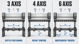
3-Axis vs 4-Axis vs 6-Axis: Quick Comparison
The axis count on a CNC press brake describes the number of machine movements the controller manages automatically. More axes mean more automated positioning — but not necessarily better value for every shop.
One important caveat before the comparison: axis-count terminology is not standardized across press-brake manufacturers. A "4-axis" or "6-axis" label does not always describe the same physical movements. The table below reflects common full-machine configurations, but axis naming conventions vary, and some suppliers count backgauge axes separately from the full machine. Always compare the actual axis list, not the number alone.
| Configuration | Common Configuration* | Main Added Capability | Typical Use |
|---|---|---|---|
| 3-axis | Y1/Y2/X | CNC backgauge depth positioning | Simple, repeatable parts with consistent gauging |
| 4-axis | Often Y1/Y2/X/R | Automatic backgauge height adjustment | Mixed flange heights, varied part families |
| 6-axis | Often Y1/Y2/X/R/Z1/Z2 | Independent lateral finger positioning | High-mix, asymmetric, or frequently changing work |
1.What Do Press Brake Axes Mean?
Before comparing axis counts, it helps to understand one critical distinction: press-brake axes are not the same as axes on a CNC milling machine or machining center.
On a milling machine, axes describe how a cutting tool moves through three-dimensional space — X, Y, Z for linear movement, and A, B, C for rotation. On a CNC press brake, the axis count typically refers to how many movements in the ram and backgauge system are CNC-controlled. Adding axes means adding automated positioning capability, not rotary or tilting tool movement.
This matters because buyers who research generic "multi-axis CNC" content may expect press-brake axis counts to work the same way. They do not.
1.1 What Each Axis Controls
| Axis | Location | Function |
|---|---|---|
| Y1 | Left ram cylinder | Controls left-side ram stroke depth |
| Y2 | Right ram cylinder | Controls right-side ram stroke depth |
| X | Backgauge carriage | Moves backgauge forward/backward to set flange depth |
| R | Backgauge vertical mechanism | Raises or lowers the backgauge fingers |
| Z1 | Left backgauge finger | Moves left finger laterally along the machine bed |
| Z2 | Right backgauge finger | Moves right finger laterally, independently of Z1 |
Y1 and Y2 are standard on synchronized hydraulic CNC press brakes, though exact configurations vary by machine design and manufacturer. The real differences between 3-, 4-, and 6-axis machines lie in what the backgauge can do — and which of those movements are driven by the CNC controller rather than the operator.
Some machines include additional controlled functions beyond this list: independent X1/X2 depth axes for each finger, dual R axes, or automated crowning. If a quotation mentions axes not covered here, confirm precisely what each one does before evaluating the machine.
1.2 Why Axis Counts Vary Between Manufacturers
This is where buyers get confused — and where a purchase decision can go wrong.
A common full-machine convention counts Y1, Y2, and all backgauge axes together:
Some suppliers, however, count and describe the backgauge system separately from the full machine. In this convention:
- A 4-axis backgauge may refer to X/R/Z1/Z2 — four backgauge movements, not counting the ram
- A 6-axis backgauge may refer to X1/X2/R1/R2/Z1/Z2 — independent depth and height for each finger, plus lateral positioning
Both conventions are in active use. Neither is wrong. What matters is that two machines both described as "6-axis" may have entirely different physical configurations depending on which counting method the manufacturer uses.
The practical implication: do not compare axis counts across suppliers without first confirming which movements each number represents. Request a line-by-line axis list — axis name, what it controls, travel range, and whether it is programmable from the controller — before finalizing any comparison.
1.3 3-Axis Press Brakes: When Is It Enough?
Common configuration: Y1/Y2/X
A 3-axis press brake provides synchronized ram control and programmable backgauge depth. For many operations, that is exactly what the work requires.
Best fit:
- Simple brackets, flat profiles, and standard panels
- Electrical cabinet blanks and door frames
- Production runs with consistent flange depths across all bends
- Stable, repeating product families where gauging requirements do not change frequently
Where manual intervention increases: Without R or Z axes, any change in backgauge height or finger position requires the operator to adjust manually. On a stable part family, this adds minimal overhead. On a mixed workload, those adjustments accumulate across a shift.
Buyer checkpoint: Review your active part drawings. If most bends need only consistent depth positioning — no height changes, no asymmetric gauging — a 3-axis configuration may be entirely sufficient for that work.
2. 4-Axis Press Brakes: When Do You Need R-Axis Control?
Common configuration: Y1/Y2/X/R
The R axis moves the backgauge fingers vertically. Its value appears when a part's bend sequence requires the gauge to sit at different heights — either between steps on the same part, or between different parts in a mixed production run.
A typical scenario: a sheet metal enclosure panel with a short front flange bent first, followed by a taller side flange. Without R-axis control, the operator repositions the backgauge height manually between steps. With R, the controller handles it automatically as part of the programmed sequence.
Best fit:
- Parts with multiple bend steps at varying heights
- HVAC sheet metal, elevator panels, stainless covers, and similar work with height variation
- Job-shop environments processing varied product sizes within the same shift
The improvement is not primarily about bend accuracy. A skilled operator on a 3-axis machine can hold the same tolerances. R-axis automation reduces setup interruptions and positional variation — particularly valuable on parts that run repeatedly or when one operator handles multiple part types.
A 4-axis configuration can be a practical middle ground for shops that need automatic backgauge height adjustment but do not require independently positioned Z fingers. Whether that applies to your workload depends on your actual drawings, not on general characterizations of the machine category.
Buyer checkpoint: Identify drawings where backgauge height changes within the bend sequence. If that accounts for a meaningful share of your production, estimate the manual adjustment time per week. That gives you a starting basis for evaluating the 4-axis premium.
3. 6-Axis Press Brakes: When Do You Need Z1/Z2?
Common configuration: Y1/Y2/X/R/Z1/Z2
Z1 and Z2 move each backgauge finger independently along the machine bed. In this common configuration, the CNC can program the fingers’ depth, height, and lateral positions for each step of the bend sequence.
A configuration with independent Z fingers may be worth evaluating for:
- High-mix production with frequent changeovers
- Asymmetric parts, irregular flanges, or narrow or off-center gauging surfaces
- Parts where finger spacing changes between bends or jobs
- Bending lines where manual repositioning limits throughput
The main value of Z1/Z2 is setup speed and repeatability on varied work. The controller can reposition the fingers automatically, reducing the need for manual adjustment between steps or jobs.
A higher axis count does not automatically improve bend accuracy. Ram precision, controller capability, crowning, tooling condition, and material consistency all affect the bending result. Backgauge axes mainly change positioning and setup capability.
A 6-axis configuration generally adds hardware and control-system complexity. Purchase price, programming requirements, and service considerations should be evaluated against the workload. For simple, repetitive parts, a 6-axis machine may provide little practical benefit over a 3- or 4-axis configuration.
Buyer checkpoint: Track how often operators reposition backgauge fingers during a typical production week and which part families require it. Compare the time and setup burden with the additional investment before specifying independent Z-axis movement.
4. How to Choose the Right Axis Configuration
The most common purchasing mistake is choosing an axis count because it sounds more capable rather than because the parts require it. A 6-axis machine running consistent parts may provide little advantage from Z1/Z2 automation. Conversely, a 3-axis machine in a high-mix environment may require frequent manual adjustments.
Start with representative drawings and the actual bending workflow.
4.1 Start With the Gauging Requirements
Review a representative sample of active part drawings. For each part, ask:
- How many bends require the backgauge to reposition within the sequence?
- Do any steps require a different backgauge height?
- Are parts asymmetric, narrow, or off-center in a way that calls for different finger positions?
- Do formed flanges, return bends, or other features limit which edge can be used for gauging?
Parts requiring only consistent depth positioning may be suitable for a 3-axis configuration. Varying gauge heights may make R-axis control useful. Asymmetric gauging or frequent finger repositioning may make Z-axis movement valuable.
4.2 Review Bend Sequence and Tool Access
Axis count is only one factor affecting whether a part can be gauged. Flanges formed earlier in the sequence can obstruct the backgauge on later steps. Return bends may require the gauge to retract, while deep boxes can create finger or tooling-clearance issues.
Before confirming a configuration, validate representative parts through the controller’s bending simulation or ask the supplier to run the sequences using your drawings. A configuration that appears suitable on paper may have limitations in an actual bend sequence.
4.3 Consider Your Production Pattern
Consider how the shop’s workload is structured:
- Are runs usually long and stable, or short and varied?
- How frequently do operators change programs, tooling, and gauge positions?
- Is the product range likely to expand into more varied contract work?
A shop anticipating more high-mix work may decide that additional axes are worth specifying upfront. A shop with a stable range of simple parts may not benefit from the additional automation. Base the decision on expected production needs rather than a general claim that more axes are better.
5. How to Calculate Whether Extra Axes Are Worth It
General claims about productivity improvements from higher axis counts may not reflect your shop’s actual production. Build the comparison from your own data:
- Identify affected part families: Which parts require the positioning changes that additional axes could automate?
- Measure adjustment frequency: How often do operators change gauge height or finger position on those parts?
- Estimate time per adjustment: Include positioning, confirmation, and any subsequent checks.
- Calculate the total burden: Multiply adjustment frequency by time per adjustment over a representative period.
- Consider quality impact: If manual repositioning contributes to first-piece rejects or rework, include that cost in the assessment.
- Compare with the configuration premium: Compare the additional machine cost with the time and setup burden that could be avoided.
This analysis will not guarantee a precise payback figure, but it can show whether the productivity case for additional axes is strong, marginal, or absent. Include controller software, offline programming, training, spare parts, service response, and planned automation integration in the total-cost comparison.
Do not accept a generic supplier payback claim as a substitute for evaluating your own parts and production data.
6. Questions to Ask Before You Buy
Use these questions when comparing press-brake quotations.
Axes and backgauge configuration:
- Which axes are included as standard, and which are optional?
- What travel ranges and programmable movements apply to X, R, Z1, and Z2?
- Are Z1 and Z2 independently programmable, or do they move as a pair?
- Does the quoted axis count include the ram axes, or are backgauge axes counted separately?
Part validation:
- Can the supplier demonstrate the proposed bend sequence using representative drawings?
- Does the controller support bending simulation or offline program verification?
- Can sample parts be tested on the quoted machine configuration before delivery?
Complete machine specification:
- What crowning system is included?
- Which safety systems are included in the quoted configuration?
- Is the tooling clamping system compatible with your existing tooling?
- What training, installation, commissioning, and after-sales support are included?
6.1 Send a Drawing Review Package
Give each supplier a consistent set of information to review:
- Representative 2D or 3D drawings for the main product families
- Material grade and thickness
- Maximum and minimum part dimensions
- Required bend-angle tolerances
- Expected production volumes and batch sizes
- Current setup challenges or quality issues
Ask suppliers to recommend an axis configuration and identify the specific drawing features that support their recommendation. This makes it easier to compare proposals based on your parts rather than on general machine descriptions.
For a related resource on machine setup and tooling, see the CNC press brake tooling and setup.
7. FAQ
Q1: Is a 4-axis press brake always better than a 3-axis machine?
Answer: No. A 4-axis configuration may add automatic backgauge height adjustment, but that feature is useful only when the parts or bend sequence require it. If they do not, a 3-axis machine may be sufficient.
Q2: Does a “4-axis” press brake always mean Y1/Y2/X/R?
Answer: Not necessarily. Some suppliers count the ram and backgauge movements together; others describe backgauge axes separately. Confirm the actual axis list rather than relying on the number alone.
Q3: When do I need Z1 and Z2 backgauge fingers?
Answer: Consider independent Z1/Z2 movement when parts require different lateral finger positions, particularly in asymmetric or high-mix production. If finger positions rarely change, the added capability may not justify its cost.
Q4: Does a higher axis count improve bend accuracy?
Answer: Not by itself. Bend accuracy also depends on the ram system, controller, crowning, tooling condition, material consistency, and process setup. Backgauge axes primarily affect positioning and setup.
Q5: Why do press-brake axis labels differ from CNC milling terminology?
Answer: Milling-machine axes describe tool or workpiece movement through linear and rotary directions. Press-brake axis counts typically describe CNC-controlled ram and backgauge movements. The numbers may look similar, but the functions differ.
Q6: Can a 6-axis press brake be a poor investment?
Answer: Yes. If parts are simple and gauging requirements stay consistent, independent finger positioning may provide little benefit. Evaluate the added cost and complexity against the adjustments it would eliminate.
Q7: Can I verify the configuration using my drawings before ordering?
Answer: Ask the supplier to review representative drawings, simulate the bend sequence, or demonstrate sample parts on the proposed configuration. This helps confirm that the listed axes suit the work before purchase.
8. Choose the Configuration That Removes Your Real Bottleneck
Axis count is a specification, not a ranking. A 3-axis machine is not inherently inferior to a 6-axis machine; each configuration suits different parts and production conditions.
Use the actual backgauge movements as the starting point:
- 3-axis may be sufficient when depth positioning and ram control cover the bend sequence.
- 4-axis may help when programmed vertical backgauge movement addresses a recurring need.
- 6-axis may help when independently positioned fingers reduce setup work on high-mix or asymmetric parts.
No axis configuration replaces the need to select the right machine capacity, bed length, controller, tooling, and process setup. Before ordering, compare the actual axis lists across suppliers and validate the proposed configuration against representative drawings.
A useful final step is to request a drawing-based configuration review and confirm what each quoted axis controls. For an article about backgauge positioning and setup.