


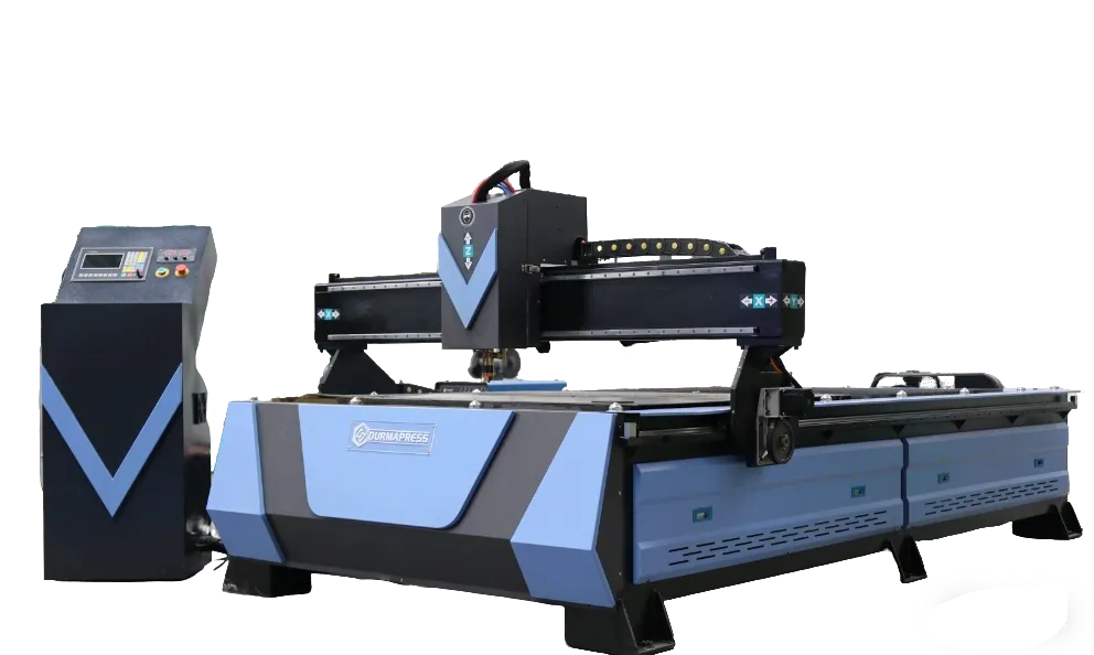
CNC Plasma Cutting: How It Works, Cutting Capacity, and Machine Selection
- Conocimientos, Noticias
- 90+ reading now
Quiénes somos
Durmapress specializes in designing, manufacturing, and selling various metal processing equipment, including bending machines, shears, punches, and laser cutting machines. The company was founded in 2014, with years of experience and technology accumulation. DurmaPress has become one of the well-known brands in China's metal processing machinery industry.




Contáctenos
Entradas recientes



Categorías
Síganos
Nuevo vídeo semanal
Table of Contents
CNC plasma cutting is one of the most practical metal cutting processes available to fabrication shops, manufacturers, and construction suppliers. It combines a high-temperature plasma arc with computer-controlled motion to cut electrically conductive metals with speed and repeatability that manual cutting cannot reliably match.
This guide explains how the process works, what it can and cannot cut, what affects cut quality, how to evaluate a CNC plasma system for your production requirements, and how it compares with laser, oxy-fuel, and waterjet cutting.
1. What Is CNC Plasma Cutting?
CNC plasma cutting uses a computer-controlled torch to cut electrically conductive metals. The torch generates a plasma arc that melts the metal at the cut point, while high-velocity gas expels the molten material from the kerf. The CNC system moves the torch along a programmed path derived from a CAD file, producing repeatable shapes without manual guiding.
The process does not require preheating in the way oxy-fuel cutting does — the plasma arc reaches working temperature almost instantly. Most systems operate on compressed air rather than bottled gas, though oxygen, nitrogen, or gas mixtures are used in specific material and quality applications.
1.1 CNC Plasma Cutting vs Manual Plasma Cutting
Manual plasma cutting uses a handheld torch guided by the operator. It suits on-site repair, rough sizing, irregular one-off shapes, and jobs where tight tolerances are not required.
CNC plasma follows a programmed toolpath. It is the right choice when part geometry is complex, dimensional consistency across a batch is required, or layout effort and cutting time need to be reduced. CNC removes operator variability from travel speed and torch angle — two common sources of inconsistency in manual work.
That said, CNC does not automatically produce perfect results. Edge quality still depends on correct parameters, clean air supply, consumable condition, and properly prepared design files.
2. How CNC Plasma Cutting Works?
Compressed air or gas flows into the torch. A high-voltage arc ionizes the gas, converting it into plasma that reaches temperatures above 20,000°C. The plasma jet melts the metal, and the gas stream expels molten material from the cut path. The CNC controller moves the torch along the programmed route as cutting progresses.
Kerf width, cut face angle, and dross level are all influenced by how accurately those variables are controlled — not just by the machine specification.
2.1 From CAD File to Finished Part
- Create or import a CAD drawing, typically as a DXF file.
- Process through CAM software to generate G-code, applying kerf compensation, lead-ins, and cut order.
- Transfer the file to the CNC controller.
- Set cutting parameters: amperage, gas pressure, torch height, and travel speed for the material type and thickness.
- Secure the workpiece and confirm grounding.
- Run a test cut on scrap material when setting up a new job.
- Inspect the first article — dimensions, holes, and edge quality — before committing to the full run.
2.2 Key Components of a CNC Plasma System
| Factor | Direct-Drive Mechanical Shear | Hydraulic Shear | CNC Shear |
|---|---|---|---|
| Main drive | Flywheel, clutch and mechanical linkage | Hydraulic cylinder and hydraulic system | CNC control with programmable positioning |
| Best for | Repetitive straight cuts | Flexible sheet-metal cutting applications | Repeated dimensions and batch production |
| Main advantage | Fast, repeatable mechanical cycles | Adjustable cutting conditions | Back-gauge repeatability and reduced setup work |
| Main limitation | Less flexible adjustment | Requires hydraulic maintenance | Higher control-system investment |
Torch height control is particularly important on production plate, which warps, has mill scale variation, or sits unevenly. Without automatic THC, height variation across a long cut directly affects bevel angle, dross level, and edge consistency.
3. What Materials Can CNC Plasma Cut?
Plasma cutting works on electrically conductive metals:
- Acero dulce — the most common material; fast, clean cuts with compressed air across a wide thickness range.
- Carbon steel and structural steel — similar behavior to mild steel; widely used in fabrication and construction.
- Acero inoxidable — cuts effectively; edge oxidation on the cut face may require consideration for weld-prep or visible surfaces. Nitrogen or specific gas mixes can improve edge appearance in those applications.
- Aluminium — higher thermal conductivity requires adjusted speed and typically higher amperage relative to thickness compared with mild steel.
- Galvanized and painted steel — plasma tolerates surface coatings better than laser cutting, though coatings affect consumable wear and may require additional ventilation.
- Copper and brass — can be cut but are more demanding due to high thermal conductivity.
Plasma cannot cut non-conductive materials. Wood, plastic, glass, rubber, and stone require a different process.
3.1 Cutting Capacity by Amperage and Material
Two specifications appear on every plasma cutter datasheet: recommended cut capacity y severance cut capacity.
Recommended cut capacity is the thickness at which the machine delivers usable edge quality at a practical production speed — suitable for welding prep, fit-up, and most fabrication applications.
Severance cut capacity is the maximum thickness the machine can cut through, but typically at reduced speed and with rough edges that require finishing. This number is always higher than recommended cut capacity and should not be used to size a machine for production work.
The table below shows typical reference values based on published manufacturer data for air plasma systems. Actual performance depends on the specific power source, torch, consumables, material condition, and required cut quality. Always verify against the system's cut charts.
| Plasma Source Amperage | Mild Steel Recommended Cut | Mild Steel Severance Cut | Stainless Recommended Cut | Typical Application |
|---|---|---|---|---|
| ~45 A | ~12 mm | ~16–19 mm | ~10 mm | Light fabrication, HVAC, thin structural |
| ~65 A | ~16–20 mm | ~25–32 mm | ~12 mm | General mixed fabrication |
| ~85 A | ~20–25 mm | ~32–38 mm | ~16 mm | Medium-heavy fabrication |
| ~105 A | ~32 mm | ~50 mm | ~20 mm | Heavy plate, structural steel |
When selecting a machine, size it against your most common material type and thickness — not the severance maximum listed in the brochure.
4. Where CNC Plasma Cutting Is Used
CNC plasma is most productive where speed, repeatability, and moderate-to-good edge quality matter more than ultra-fine tolerances.
4.1 Fabrication and Manufacturing
Brackets, gussets, flanges, frames, mounting plates, machine guards, and custom components are standard CNC plasma work. For repeat parts or medium-volume runs, a CNC table eliminates layout time, reduces operator variation, and cuts faster than manual methods.
4.2 Construction, Structural Steel, and Repair Work
Base plates, beam connection plates, stiffeners, gussets, and repair patches are common structural applications. Where the same profile repeats across multiple projects, CNC plasma reduces marking and cutting errors significantly. For on-site or irregular repair work, a manual plasma cutter remains more practical.
4.3 Automotive, Agricultural, and Equipment Parts
Chassis brackets, suspension components, mounting plates, guards, and custom panels are within CNC plasma's capability. Cutting directly from a digital file avoids manual layout and reduces dimensional errors across a batch.
4.4 Signs, Decorative Metalwork, and Custom Projects
Metal signage, decorative gates, wall art, furniture components, and custom panels are common applications. The practical constraint is feature size: kerf width and minimum achievable hole diameter limit how fine the detail can be relative to overall part dimensions. Designs intended for laser cutting may need modification before translating well to plasma.
5. CNC Plasma Cutting Capability and Practical Limits
Where CNC plasma delivers clear value:
- Fast cutting speed on conductive metals from approximately 1 mm to 50+ mm depending on amperage
- Lower equipment cost than fiber laser or waterjet systems of comparable capacity
- Versatility across mild steel, stainless, aluminium, copper, and brass from a single machine
- Better tolerance of surface condition than laser — mill scale, light rust, and paint have limited impact in most situations, though severity matters
- Consistent part geometry and batch repeatability from programmed files
- Efficient material use through software nesting
Where CNC plasma has practical limits:
- Dimensional tolerances are typically ±0.5–1.5 mm on entry-level to mid-range systems; high-definition plasma with precision motion control achieves tighter results, but tolerance depends on equipment grade, material condition, part geometry, and process setup
- A heat-affected zone is produced adjacent to the cut edge
- Some dross on the cut underside requires removal where fit-up is critical
- Minimum achievable hole diameter is constrained — see the design section below
- Not suitable for non-conductive materials
For a detailed comparison of when laser, oxy-fuel, or waterjet is the better choice, see the process comparison section later in this article.
6. What Affects CNC Plasma Cut Quality?
Machine brand matters less than how the machine is set up and maintained. Cut quality is determined by the interaction of several variables the operator controls directly.
6.1 Amperage, Travel Speed, and Torch Height
Amperage should be matched to material type and thickness using the cut charts for the specific plasma source. Running higher-than-necessary amperage widens the kerf, increases heat input, and shortens consumable life. Running too low produces incomplete cuts or heavy dross. There is no universal amperage-to-thickness formula that applies across all systems — the plasma source manufacturer's cut charts are the correct reference.
Travel speed is the variable operators adjust most in practice. The visual indicator of correct speed is the behavior of sparks on the underside: at correct speed, they trail at a slight backward angle. Sparks angling sharply backward mean the speed is too fast; near-vertical sparks or grooves in the plate indicate too slow. Too slow: wider kerf, excess dross, more distortion on thin material. Too fast: incomplete penetration, rough edges, inconsistent cut depth.
Torch height controls the standoff between the nozzle exit and the plate surface. Too low risks nozzle contact and premature wear; too high reduces arc focus, producing a wider kerf, worse bevel angle, and reduced cut quality. Torch height control systems adjust this automatically during the cut, which is particularly important on warped or uneven plate.
6.2 Kerf, Dross, Bevel, and Heat-Affected Zone
| Characteristic | What It Is | Production Consequence |
|---|---|---|
| Kerf | Width of material removed during cutting | Must be compensated in CAM; varies by amperage and material |
| Dross | Resolidified metal on the cut underside | Requires removal before assembly or weld fit-up |
| Bevel | Angle on the cut face (0° = square edge) | Affects mating part fit; excessive bevel indicates a settings or consumable problem |
| Heat-affected zone (HAZ) | Material property change adjacent to cut edge | Can affect weld procedures, distortion on thin sheet, and structural application requirements |
These are not just aesthetic concerns. Heavy dross increases grinding labor per part. Excessive bevel creates fit-up problems that slow welding. A wide HAZ may affect weld procedure qualification on structural components.
6.3 Air Quality and Consumable Condition
Compressed air quality requirements should follow the plasma source manufacturer's specifications. Moisture causes arc instability, accelerates electrode erosion, and leaves contaminated edges. Oil and particulates score the nozzle orifice. The appropriate filtration, moisture separation, and drying solution depends on compressor type, ambient humidity, and plasma source requirements — a single configuration is not universal.
Consumable wear is gradual but cumulative. As the electrode erodes, arc stability drops. A worn nozzle produces a wider, less focused plasma jet. Both degrade cut quality before causing visible torch failure. Replacement intervals vary by torch type, amperage, pierce frequency, and air quality — check the specific torch manufacturer's guidance. Running consumables to failure rather than replacing on schedule creates a period of poor-quality output before the operator notices the problem.
7. Common CNC Plasma Cutting Problems: Causes and Fixes
The factors that drive each problem are covered in the previous section. This table focuses on identifying the symptom and working through the most likely causes in order.
| Problem | Symptom | Check First | Check Next | Check Last |
|---|---|---|---|---|
| Heavy dross | Thick, hard residue on cut underside | Travel speed too slow | Amperage too high for thickness | Wet air or worn consumables |
| Excessive bevel | Cut face angled rather than square | Torch height too high | Worn nozzle orifice | Torch mounting not perpendicular |
| Incomplete cuts | Arc cuts partway through; no full separation | Travel speed too fast | Amperage too low | Air pressure insufficient at torch inlet |
| Short consumable life | Electrode or nozzle fails well before expected | Compressed air wet or contaminated | Pierce height incorrect (too low) | Consumable type not matched to plasma source |
| Poor hole quality | Holes oval, tapered, or heavily drossed | Hole diameter too small for material thickness | Lead-in geometry incorrect | Travel speed or THC settings off for hole profile |
7.1 Heavy Dross
If dross is thick and low-melting, travel speed is usually too slow. If it is hard and high, amperage may be too low or air quality is the issue. Always check consumable condition before making parameter changes — a worn electrode can produce dross symptoms regardless of speed setting.
7.2 Angled or Beveled Edges
The most common cause is torch height set too high. A worn nozzle orifice produces an asymmetric arc that creates bevel even at correct height. Calibrate THC at the start of each production session and replace the nozzle on the schedule specified by the torch manufacturer.
7.3 Incomplete Cuts
Verify travel speed first — too fast is the most frequent cause. Then check amperage against the cut chart. Measure air pressure at the torch inlet rather than only at the compressor outlet: line pressure drop can be significant enough to reduce arc performance without being obvious at the supply end.
7.4 Short Consumable Life
The four most common causes are wet compressed air, incorrect pierce height (too low causes nozzle spatter damage), excessive pierce amperage, and using consumables not matched to the plasma source. Track consumable life per pierce count and per arc-on hour. When life drops below baseline, investigate air quality and pierce settings before assuming the consumables are defective.
8. CNC Plasma Machine Types and Selection Factors
Selecting the right CNC plasma system means matching the configuration to the work you do most — not to occasional maximum requirements.
8.1 Machine Selection Checklist
| Selection Factor | What to Verify |
|---|---|
| Material and thickness | Most common material type, daily cutting thickness range, maximum occasional thickness |
| Required cut quality | Dimensional tolerance needed, acceptable dross level, secondary finishing in your process |
| Plasma power source | Rated amperage, published recommended and severance cut capacity by material, pierce capability |
| Arc start type | Pilot arc or contact start required for CNC — high-frequency start interferes with electronics |
| Working table size | Working area vs. standard sheet size; loading and unloading clearance |
| Torch height control | Automatic THC capability and response to plate warping |
| Motion system | Gantry rigidity, drive type, positional repeatability specification |
| Fume control | Downdraft or water table, local extraction requirements |
| Software | DXF import, kerf compensation, nesting, lead-in configuration, file workflow |
| After-sales support | Installation, training, spare parts availability, service response time |
8.2 Table Size and Machine Format
Full-size gantry tables suit production environments. They accept standard sheet sizes (1500 × 3000 mm, 2000 × 6000 mm, and larger), support long cuts without repositioning, and integrate with water tables or downdraft extraction.
Compact or portable CNC systems — small-footprint tables and articulated arm units — suit smaller workshops or budget-constrained setups. They trade throughput and sheet capacity for lower cost and faster setup.
8.3 Plasma Power Source and Amperage
Amperage is the most important technical specification. The reference values in the cutting capacity table earlier provide a starting point, but always verify against the specific power source's published cut charts for your material.
For production environments, duty cycle matters. A machine rated at 60% duty cycle at maximum amperage requires rest time between long cuts. Choose a unit with amperage headroom above your normal operating current, or a higher duty-cycle rating, for continuous production.
Confirm the plasma source includes CNC-compatible outputs — specifically a divided arc voltage signal for torch height control — before assuming compatibility with a cutting table. Pilot arc or contact start is required; high-frequency start systems interfere with electronics and are not suitable for CNC use.
8.4 Torch Height Control and Motion Quality
Torch height control is not optional for production work. Even minor plate warping over a long cut produces significant height variation, which translates directly into inconsistent bevel angle, variable dross, and irregular edge quality.
Motion system quality — gantry rigidity, drive precision, and motor performance — determines how accurately the torch follows the programmed path through corners, curves, and hole profiles. Request the manufacturer's positional repeatability specification and inspect sample cuts from the machine at your material thickness where possible.
8.5 Software, File Handling, and Operator Workflow
Key questions when evaluating software:
- Does the controller accept DXF directly, or is a separate post-processing step required?
- Is kerf compensation handled automatically in CAM?
- Are lead-in and lead-out parameters configurable per material and thickness?
- Does the system support nesting?
- What is the learning curve for your operators?
In high-mix environments with frequent file changes, a streamlined software workflow often has more daily production impact than marginal differences in machine specification.
9. CNC Plasma Cutting Cost: What Drives the Price Per Part
9.1 Initial Investment
A complete CNC plasma system typically includes the cutting table and controller, plasma power source (sometimes sold separately), air compressor, inline filtration and moisture control, fume extraction or water table, CAD/CAM software, and installation and training.
Entry-level compact systems have a significantly lower acquisition cost than industrial gantry tables with high-definition plasma sources. Comparing machines on purchase price alone — without accounting for plasma source quality, software capability, and support — is one of the most common procurement mistakes.
9.2 Operating Cost Per Part
Cost per part = Material cost + Cutting cost + Consumables + Labor + Finishing cost
The main drivers:
- Material — typically the largest variable cost; nesting efficiency directly affects this
- Cutting length and pierce count — more pierces and longer arc-on time accelerate consumable wear
- Material type and thickness — stainless steel and thicker plate cut more slowly, increasing cost per linear metre
- Consumable replacement frequency — driven by pierce count, arc-on hours, and air quality
- Compressed air — compressor electricity and filtration maintenance
- Secondary finishing — dross removal, deburring, bevel correction; often invisible in cutting cycle time but significant in total labor
To populate the cost model, request published cut speeds and consumable life estimates from the plasma source manufacturer for your specific material and thickness. These provide a reliable starting benchmark.
9.3 How to Reduce CNC Plasma Cutting Cost
- Improve nesting efficiency — even a 5–10% gain in material utilization generates measurable savings at volume
- Reduce pierce count — common cutting in CAM reduces both pierces and total cutting length
- Use correct parameters — cutting too slowly increases HAZ and dross, adding finishing time
- Maintain air quality — regular filter maintenance is one of the lowest-cost ways to extend consumable life
- Replace consumables on schedule — waiting for failure produces a period of poor-quality output before detection
- Design parts for plasma — see the section below
10.Design Tips for Better CNC Plasma Parts
Results on the machine are shaped substantially by decisions made before the arc starts.
10.1 Account for Kerf Compensation
The plasma arc removes a band of material along the cut path. Without kerf offset applied in CAM, finished parts will be undersized by approximately half the kerf width on each edge. The correct offset value must be entered for the specific plasma source, amperage, and material being cut.
If your shop uses multiple machines or amperage settings, kerf width varies between configurations. Maintaining documented kerf compensation values per configuration is basic process control. Inconsistent compensation is a common cause of systematic dimensional errors across a production run.
10.2 Hole Size and Small Feature Limits
A commonly used working guideline is that a cleanly cut hole should have a diameter no smaller than the material thickness — for example, a 10 mm hole in 10 mm plate. Below this ratio, the arc cannot maintain the correct profile, and holes come out oval, tapered, or heavily drossed.
This ratio is an experience-based reference, not a fixed physical limit. Achievable hole quality also depends on the plasma system, consumable type, cutting speed, lead-in geometry, and THC performance.High-definition plasma cutting systems with true-hole technology can achieve better results at smaller diameter-to-thickness ratios, but require compatible torch and controller features.
For precision fits — bolt holes, bushing locations, pivot points — the most reliable production approach is to plasma-cut a pilot hole and finish by drilling or reaming.
10.3 Lead-Ins, Cut Order, and Nesting
Lead-ins start the pierce away from the finished edge, then curve into the cut line, preventing the visible divot that a direct entry leaves. For internal holes, a spiral or curved lead-in improves roundness and reduces entry-point defects.
Cut order affects both quality and safety. Internal features — holes, slots, cutouts — should be cut before the outer profile. Cutting the profile first allows the part to shift as surrounding material loses support, distorting internal features or causing the torch to catch a moving edge.
Nesting determines how efficiently parts are arranged on the sheet. Good nesting reduces material waste and lowers cost per part. Manual review of automatic nesting is worthwhile for high-value material or complex part mixes where small layout changes significantly affect yield.
11. Safe and Efficient Operation
11.1 Basic Operating Workflow
- Inspect the material — check for warping, contamination, or dimensional issues.
- Secure the workpiece — flat on the table with grounding to the machine earth, not to the offcut side.
- Check consumables — inspect electrode, nozzle, and shield before starting a production run. Replace worn parts.
- Verify air/gas supply — confirm pressure at the torch inlet is within the required range. Check the inline filter has been drained. Line pressure drop between compressor and torch can be significant; measure at the inlet.
- Load and verify the file — confirm file version, kerf compensation value, lead-in settings, and cut order.
- Confirm parameters — amperage, travel speed, and torch height against the cut chart for the current material and thickness.
- Run a test cut — on scrap material when setting up a new job or changing material type.
- Monitor the first cut — arc stability, kerf width, dross, and edge quality.
- Inspect the first part — dimensions, holes, and edge condition before starting the production run.
11.2 Essential Safety Precautions
CNC plasma cutting produces UV and infrared radiation, high-velocity sparks, metal fume, nitrogen oxides, and ozone. Workpieces and offcuts remain dangerously hot for several minutes. Always follow the specific guidance in your equipment manual and comply with occupational safety regulations applicable in your location.
- Eye and face protection — appropriate shade lens for the cutting intensity; do not observe the arc without correct protection.
- Protective clothing — leather gloves and flame-resistant workwear; avoid synthetics near the cutting zone.
- Ventilation and fume extraction — required in all enclosed environments; cutting coated or stainless steel produces additional hazards requiring enhanced controls.
- Fire prevention — clear combustibles from the cutting area; sparks travel well beyond the immediate cut zone.
- Grounding — earth clamp to the part being retained, not the offcut.
- Hot parts — use gloves when handling cut parts and offcuts.
12. CNC Plasma Cutting vs Laser, Oxy-Fuel, and Waterjet
The table below shows typical capabilities for general metal fabrication. Actual performance depends on machine specification, material, part geometry, and required quality — these are reference ranges, not guaranteed specifications.
| Factor | Plasma | Laser | Oxy-Fuel | Waterjet |
|---|---|---|---|---|
| Typical materials | Conductive metals | Metals and non-metals | Carbon steel primarily | Most materials |
| Typical thickness range | ~1–50+ mm | ~0.5–25 mm | ~6–300+ mm | ~0.5–200 mm |
| Typical dimensional tolerance | ±0.5–1.5 mm standard; tighter with HD plasma and precision motion | ±0.05–0.2 mm | ±1–3 mm | ±0.05–0.2 mm |
| Edge quality | Good; some dross; bevel possible | Excellent; minimal HAZ on thin sheet | Rough; typically requires grinding | Excellent; no HAZ |
| Speed on 10 mm mild steel | Fast | Fast | Slow — preheating required | Slow |
| Equipment cost | Medium | High | Low | High |
| Operating cost | Low–medium | Medium–high | Low | Medium–high |
| Heat-affected zone | Moderate | Small on thin sheet | Large | None |
| Tolerance of surface condition | Good; handles mill scale, light rust | Poor; sensitive to contamination | Moderate | Moderate |
12.1 CNC Plasma vs Laser Cutting
Laser cutting offers better dimensional accuracy and cleaner edges, making it the preferred choice for precision sheet metal components, thin stainless steel, and parts where edge finish is critical. It is also better suited to very fine detail work on thin material.
Plasma's practical advantages are equipment cost, thickness range, and surface tolerance. A CNC plasma system for general fabrication costs a fraction of a comparable fiber laser. For shops primarily cutting mild steel plate in the 6–25 mm range, plasma typically provides better return on investment.
12.2 CNC Plasma vs Oxy-Fuel Cutting
Oxy-fuel works effectively only on carbon steel, requires preheating before cutting, produces a larger HAZ, and leaves rough edges that typically need grinding. Plasma cuts all conductive metals without preheating, with a narrower kerf and smaller HAZ.
Oxy-fuel retains a practical advantage on very thick carbon steel plate where depth exceeds plasma's economical range. For material below approximately 25–30 mm, plasma is generally faster, cleaner, and more versatile for fabrication applications.
12.3 CNC Plasma vs Waterjet Cutting
Waterjet introduces no heat into the workpiece, making it the right choice where a heat-affected zone is not acceptable: hardened steel, heat-sensitive alloys, composites, and non-metal materials. It also achieves higher precision, comparable to laser.
The tradeoffs are cutting speed — waterjet is significantly slower than plasma across most metal thicknesses — and operating cost, as abrasive consumption and pump maintenance add to running costs. For metal fabrication where heat is acceptable and cost efficiency matters, plasma is the more productive solution.
13. Is CNC Plasma Cutting Right for Your Operation?
CNC plasma is a strong fit for fabrication shops, manufacturers, and construction suppliers that cut conductive metals regularly and need better dimensional consistency, shorter production time, and more efficient material use than manual cutting provides.
Choose CNC plasma if:
- You regularly cut mild steel, stainless steel, or aluminium across a range of thicknesses
- Part geometry varies, repeat batches are common, or manual layout is a production bottleneck
- Equipment cost is a constraint — plasma delivers capable performance at a lower investment than laser or waterjet for general fabrication
- Material surface condition is variable — mill scale, rust, and light coatings are acceptable in your process
Consider an alternative process if:
- Tolerances tighter than approximately ±0.3 mm are required without secondary finishing
- Zero heat-affected zone is critical — hardened materials, heat-sensitive alloys, composites
- Precision hole profiles must meet assembly requirements without drilling
- Non-conductive materials are part of the work scope
- Thin sheet demands laser-quality edges for visible or precision assemblies
Many production environments run CNC plasma alongside at least one other cutting process. Correctly routing work to the most appropriate process is where real efficiency comes from. If you are evaluating equipment for a mixed-production environment, Máquina de corte por plasma CNC product specifications can help clarify the right configuration for your material mix.
14.FAQ
Answer: Cutting capacity depends on plasma source amperage, material type, and required edge quality. A 45 A system typically handles up to around 12 mm recommended cut on mild steel; an 85 A system reaches approximately 20–25 mm. Higher-amperage industrial systems cut 32 mm and beyond at recommended quality. Always verify both recommended cut and severance ratings in the manufacturer's cut charts — the recommended cut figure is what matters for production work, not the severance maximum.
Answer: Accuracy depends on machine grade, motion system quality, plasma source type, part geometry, material condition, and process setup. Entry-level to mid-range systems typically achieve ±0.5–1.5 mm on production parts. High-definition plasma with precision motion control achieves tighter results, but published tolerance figures should be verified under conditions comparable to your actual work. Tolerance varies meaningfully between equipment grades — no single figure applies to all CNC plasma systems.
Answer: Yes. Both are electrically conductive and cut effectively with plasma. Stainless steel cut with air plasma may show edge oxidation on the cut face; nitrogen or gas mixes improve appearance where required. Aluminium requires adjusted speed and higher amperage relative to thickness compared with mild steel. Both materials are routine on a properly configured system.
Answer: Standard plasma produces a wider arc and broader kerf — adequate for general fabrication but limiting on hole diameter and edge quality. High-definition plasma uses a more precisely constrained arc, producing a narrower kerf, better hole quality, lower bevel angles, and improved fine-feature capability. HD systems require compatible torches, controllers, and motion systems to realize their potential and carry a higher equipment cost. For structural plate where edge finish is not critical, standard plasma is often the more cost-effective choice.
Answer: Most systems use compressed air as the plasma and shield gas. Clean, dry air is essential — moisture causes arc instability, reduces cut quality, and shortens consumable life. Filtration and drying requirements should follow the plasma source manufacturer's specifications. Some applications use oxygen, nitrogen, or gas mixtures for specific material and quality requirements.
Answer: Use the selection checklist in the machine selection section of this article as a starting framework. The most important factors to verify are: plasma source recommended cut capacity for your material and thickness, arc start type (pilot arc required — not high-frequency), THC capability, motion system repeatability specification, software file compatibility including DXF import and kerf compensation, table working area versus your standard sheet size, and after-sales support including parts availability and commissioning assistance.
Answer: For most general metal fabrication above 6–8 mm, CNC plasma requires lower initial investment and lower operating cost than fiber laser. On thin sheet below 3–4 mm, high-volume fiber laser may be more cost-effective due to speed advantage and lower consumable cost at those thicknesses. The comparison depends on material type, thickness distribution, part complexity, required edge quality, volume, and total cost including secondary finishing — not cutting cycle time alone.
15.Conclusion
CNC plasma cutting is a well-proven process for fabrication shops and manufacturers that cut conductive metals across a range of thicknesses. It delivers a practical combination of cutting speed, material versatility, and equipment cost that is difficult to match with laser or waterjet at equivalent production volumes on plate and sheet metal.
The difference between a system that performs consistently and one that underperforms is mostly process discipline: parameters matched to the plasma source's cut charts, clean and dry compressed air, consumables replaced on schedule, and design files prepared with kerf compensation and cut order defined before the arc starts.
Before committing to a system, map your most common material, daily thickness range, required dimensional tolerance, and finishing expectations against what the process realistically delivers at different amperage levels and machine grades. Where plasma fits — which covers the majority of general fabrication work — it typically provides the best balance of capability, throughput, and cost available at its price point. Where tolerances or material types push beyond its practical range, a different process or combination of processes will be the more productive choice.