



Press Brake Proportional Valve: Working Principle, Synchronization, and Fault Diagnosis
- Conocimientos
- 90+ reading now
Quiénes somos
Durmapress specializes in designing, manufacturing, and selling various metal processing equipment, including bending machines, shears, punches, and laser cutting machines. The company was founded in 2014, with years of experience and technology accumulation. DurmaPress has become one of the well-known brands in China's metal processing machinery industry.




Contáctenos
Entradas recientes


Categorías
Síganos
Nuevo vídeo semanal
Table of Contents
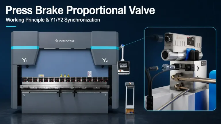
On an electro-hydraulic press brake, the press brake proportional valve is the component that translates a CNC command into controlled hydraulic motion. It determines how fast the ram moves, how much force it applies, and whether the left and right cylinders stay in sync throughout a bend.
This guide covers how the valve works within the full hydraulic control chain, how it enables Y1/Y2 synchronization, what causes it to fail or behave unexpectedly, and what to verify before replacing one.

1. What Is a Press Brake Proportional Valve?
A proportional valve is an electrically controlled hydraulic valve that can operate at any intermediate position within its range—not just fully open or fully closed. The output changes continuously in response to the command signal, which is why the same valve can meter a slow bending speed, hold a programmed pressure, and release oil at a controlled rate during decompression, all within a single bending cycle.
The standard comparison—proportional valve as a dimmer versus a conventional on/off solenoid valve as a light switch—is accurate at the conceptual level. The important caveat is that "proportional" does not mean perfectly linear. Actual hydraulic output also depends on the pressure difference across the metering edge, available pump flow, oil temperature, valve deadband, and load conditions. The valve is a controllable element in a larger system, not a standalone guarantee of ram accuracy.
On a press brake, proportional valves are typically organized by function:
- Proportional directional valves control which flow paths are active and meter how much oil moves in each direction, governing ram speed and movement direction.
- Proportional pressure valves regulate the pressure threshold in part of the circuit, controlling the hydraulic force available to the cylinders.
- Combined valve blocks integrate multiple functions into a manifold to reduce external plumbing and improve response.
These are different devices performing different roles. A single proportional valve does not simultaneously and independently control direction, speed, and pressure. The hydraulic schematic, not the component name alone, shows what each valve actually does in a given machine.
2. How Does a Press Brake Proportional Valve Work?
The valve converts an electrical command into a change in spool or poppet position, which alters how oil passes through the hydraulic circuit. The complete process involves four stages:
1. Command and driver The CNC or motion controller generates a variable command signal—commonly ±10 V, 0–10 V, or 4–20 mA depending on the valve electronics. A valve driver (also called an amplifier), either external or integrated into the valve body as onboard electronics (OBE), converts that signal into regulated current through the solenoid coil.
2. Solenoid and spool movement Coil current generates a magnetic force on the armature, which pushes the spool against spring and hydraulic forces. The spool shifts proportionally to the net force acting on it, changing the overlap between spool lands and port passages.
3. Hydraulic metering As the spool moves, it progressively uncovers the connections between the pressure port, tank port, and actuator ports. A larger opening generally allows more oil to pass—but only when the pressure difference across that opening and the pump's available delivery support it. Hydraulic power, not the electrical command itself, moves the cylinders.
4. Feedback and correction Some valves include an internal spool-position sensor that measures actual spool travel. The driver compares this measurement to the command and corrects the drive current until they match. This inner loop reduces the effect of mechanical friction and hysteresis on the valve's metering behavior.
This last point matters for troubleshooting: internal spool feedback corrects the valve element's position. It does not confirm that the expected flow reached the cylinders, or that the ram followed its programmed target. Those require a separate, external measurement—which is what the linear scales on the machine provide.
2.1 Two Types of Hydraulic Actuation
Direct-operated valves have the solenoid acting on the main spool itself. This is straightforward but limits practical flow capacity, because the solenoid must overcome the full hydraulic forces on the main spool.
Pilot-operated valves use a small solenoid-driven pilot stage that directs oil into control chambers. The resulting pressure difference moves the larger main spool with relatively modest electromagnetic force, making this design suitable for higher-flow applications. The trade-off is an added dependency: the pilot circuit needs adequate supply pressure and a clear drain path. Low pilot pressure can prevent the main spool from reaching its commanded position even when the solenoid is energized correctly.
This distinction is relevant for diagnosis—if a high-flow pilot-operated valve fails to respond, pilot supply conditions should be checked alongside the electrical command.
3. How Proportional Valves Control a Press Brake Bending Cycle
The valve's role and the relevant hydraulic variables change at each stage of a bend. The sequence below follows a typical down-acting press brake; the exact circuit arrangement depends on the specific machine design.
Rapid approach — The ram descends quickly. Depending on machine design, pump flow, gravity assistance, or a prefill circuit supplies oil to the expanding cylinder chamber. Where a prefill valve is used, it must operate correctly and transition cleanly as the circuit switches to bending pressure.
Speed changeover — At the programmed position, the CNC reduces the command to decelerate the ram before tool contact. This transition must happen before the tool reaches the workpiece; a delayed changeover transfers shock load to the tooling, the sheet, and the machine structure.
Doblar — The tool contacts the material. Workpiece resistance builds pressure in the working cylinder chamber while the proportional valve meters controlled flow to continue penetration at the programmed rate. Rising pressure at this stage is a response to increasing load resistance, not a switch to a different control mode unless the program specifies pressure control.
Bottom position or dwell — The ram holds at a programmed depth or pressure condition. In depth hold mode, the target is a fixed position and pressure may change as the workpiece and machine settle. In pressure hold mode, the target is a pressure value and minor ram movement may be permitted. Load-holding valves in the circuit retain the position with minimal continuous flow.
Decompression — Stored hydraulic energy and machine frame deflection are released progressively before the return begins. Skipping or rushing this stage causes hydraulic shock, audible bang, and potential workpiece movement. A dedicated decompression valve, a proportional metering path, or both can perform this function.
Return — Pump flow enters the rod-side chamber to lift the ram. This stage requires pressure to overcome ram weight and friction—it is not passive. Oil leaving the cap-side chamber returns through the available discharge paths, which may include a reopened prefill valve on some machines.
4. Y1/Y2 Synchronization: How Proportional Valves Keep the Ram Parallel
This is the function that most directly connects the press brake proportional valve to production accuracy. On an electro-hydraulic press brake, the two hydraulic cylinders—labeled Y1 (left) and Y2 (right)—are controlled independently by separate proportional valves. Synchronization is achieved through closed-loop position control, not mechanical coupling.
The closed-loop process:
- The CNC generates a target position at each point in the stroke.
- Linear scales on each side of the machine continuously measure actual cylinder position.
- The controller compares each measured position to the target and calculates a position error for Y1 and Y2 independently.
- It adjusts the command to each proportional valve to correct those errors—hundreds of times per second during the stroke.
During an off-center bend, one cylinder carries more load and may lag slightly. The CNC detects this through the position error and applies a higher command to the lagging side. The result is that Y1 and Y2 commands are frequently different from each other—this is normal corrective action, not evidence of a valve fault.
4.1 Spool Position Feedback vs. Ram Position Feedback
This distinction is important for understanding what the valve's internal sensor actually controls—and what it does not.
| Feedback Type | What It Measures | What It Cannot Confirm |
|---|---|---|
| Spool position feedback (internal, inside the valve) | Actual spool travel relative to the commanded position | Whether the expected flow reached the cylinder; whether the ram followed its target |
| Ram position feedback (external, from linear scales on the machine) | Actual cylinder or ram displacement at the measurement point | Correct hydraulic pressure, bend angle, or tool penetration along the full bend length |
A valve with spool-position feedback uses an inner control loop to hold the spool at the commanded position more accurately. The machine's outer loop—driven by linear scale data—corrects the overall ram position. Both loops run simultaneously on a well-configured electro-hydraulic machine, but they act on different parts of the system.
A correctly positioned spool does not guarantee a correctly positioned ram. Leakage downstream of the valve, an incorrectly calibrated linear scale, or insufficient pump flow can all produce a ram-position error even when the valve's internal feedback is working correctly.
4.2 Electro-Hydraulic vs. Torsion-Bar Synchronization
Torsion-bar synchronization connects the left and right sides of the ram mechanically through a steel shaft. The two sides are physically constrained to move together. This approach requires no electronic feedback and no proportional valve control, which keeps the machine simpler and less expensive. The limitation is that the bar cannot distinguish between correct coupling and an eccentric load forcing the bar to twist. Over time, sustained off-center loading causes permanent deformation, and the resulting change in parallelism cannot be corrected automatically.
Electro-hydraulic synchronization replaces the mechanical link with electronic measurement and independent valve control. The CNC can detect a developing Y1/Y2 discrepancy within a single stroke and correct it before it becomes measurable at the workpiece. This makes the machine capable of handling off-center bends—where the punch does not engage the plate symmetrically—without risk of shaft damage, and without the need for manual parallelism correction over time.
| Torsion-Bar | Electro-Hydraulic | |
|---|---|---|
| Synchronization method | Mechanical steel shaft | Dual independent proportional valves with position feedback |
| Off-center load handling | Limited; sustained eccentric loading damages the shaft | Handled through independent Y1/Y2 correction |
| Repositioning accuracy | Typically ±0.1 mm or greater | Typically ±0.01 mm or better |
| Self-correction over time | None | Continuous; adjusts every stroke |
| Typical application | Simpler, economy-tier press brakes | CNC electro-hydraulic press brakes for precision bending |
4.3 Why Proportional Valve Accuracy Does Not Equal Bend Angle Accuracy
Ram position accuracy and finished bend angle are related but not the same thing. Even with perfectly synchronized Y1 and Y2 positions, the unloaded workpiece angle depends on:
- Material thickness and strength variation within a batch
- Springback—the partial elastic recovery after the ram retracts; different alloys and tempers spring back differently
- Tool geometry—punch radius, die opening, and shoulder radius all influence the relationship between ram depth and finished angle
- Machine frame deflection under bending load, which changes effective tool penetration near the center of a long bend relative to the ends
- Coronación—bed compensation for frame deflection, which operates independently of Y1/Y2 synchronization
Position control through proportional valves gets the ram to the right depth on both sides. Achieving a specific finished angle also requires validated tooling, material compensation, and angle measurement. For high-accuracy work, an angle-feedback system closes the loop on the actual workpiece rather than relying on depth alone. For electro-hydraulic press brake selection, understanding what the synchronization system controls—and what it does not—prevents unrealistic accuracy expectations.
5. Proportional Valve vs. Servo Valve: What the Difference Actually Means
The common framing—proportional valves for lower precision, servo valves for higher precision—is an oversimplification that can lead to incorrect specification decisions.
Both valve types provide continuously variable hydraulic control. The meaningful differences lie in the design parameters that govern dynamic behavior:
| Characteristic | Proportional Valve | Servo Valve (High-Performance) |
|---|---|---|
| Spool overlap | Positive overlap typical; produces a deadband around the null position | Zero or negative overlap typical; near-zero deadband |
| Response and bandwidth | Moderate; adequate for most industrial press brake cycles | Higher; suited to demanding fast closed-loop applications |
| Hysteresis | Present; reduced but not eliminated by electronics | Minimized by tighter manufacturing tolerances |
| Internal position feedback | Available on many current models (OBE designs) | Common; often the standard configuration |
| Contamination sensitivity | Tolerant of typical industrial cleanliness (ISO 4406 Class 16–18 typical) | Requires stricter cleanliness (often Class 15 or better) |
| Commissioning complexity | Moderate | Higher; tighter system design requirements |
| Typical press brake use | Ram speed control, Y1/Y2 synchronization, pressure control | Specialized or very high-dynamic applications |
The key clarification: proportional valves can include internal spool-position feedback and operate as part of a closed-loop system. The difference between a modern proportional valve with OBE and a servo valve is therefore not simply open-loop versus closed-loop. It is a difference in spool overlap, hysteresis, contamination tolerance, and dynamic response at the design level.
For the vast majority of production press brakes, a well-specified proportional valve system delivers more than adequate performance. The practical argument for servo valves in a press brake context is a specific dynamic requirement or accuracy target that the proportional system cannot reliably meet—not a general assumption that servo is always better.
When evaluating an electro-hydraulic press brake specification, ask specifically which valve brand and series is used, what the spool configuration is, and whether the valve includes internal position feedback rather than accepting "servo proportional" as a meaningful specification by itself.
6. Troubleshooting: Distinguishing Proportional Valve Faults from Other Hydraulic Problems
The most useful troubleshooting principle: a proportional valve fault is a diagnosis of last resort, not a starting assumption. Most symptoms that appear to implicate the valve originate elsewhere in the electrical, hydraulic, or mechanical system.
Before suspecting the valve, record:
- En exact alarm codes and their sequence
- En affected cycle stage: approach, changeover, bending, hold, decompression, or return
- CNC display values: commanded vs. measured position for Y1 and Y2, commanded vs. measured pressure where available
- Recent changes: oil, filters, sensors, tooling, parameter adjustments
- Oil temperature at the time of the fault
Do not run repeated cycles or change parameters to gather additional evidence. Preserve the fault record for qualified service review.
6.1 How to Separate Valve Faults from System Faults
The following framework helps assign a symptom to the correct system layer before any hardware is touched.
Step 1 — Check the electrical command first
Measure the command signal at the valve connector under the fault condition. If the command signal is absent or incorrect, the fault is upstream of the valve: check the CNC output, driver module, wiring continuity, connector condition, and enable logic. A valve cannot respond correctly to a signal it is not receiving.
Step 2 — Check hydraulic supply conditions
If the command signal is correct and the valve is energized, verify system pressure and filter status. Low supply pressure, a clogged filter, or a restricted inlet line limits what any valve can deliver regardless of its condition. Many apparent valve faults resolve after a filter change or after confirming that the hydraulic pump is maintaining specified pressure at load.
Step 3 — Evaluate the symptom against the cycle stage
- A fault appearing only during rapid approach points toward filling capacity, prefill valve behavior, or pump delivery—not proportional valve metering.
- A fault appearing only under bending load raises questions about pressure control, leakage under pressure, and whether the cylinder can develop the required force.
- Drift during the hold stage points toward cylinder seal bypass, directional valve leakage, or load-holding device condition—the proportional valve is typically not responsible for holding load.
- Decompression shock or bang is almost always a decompression valve or sequence timing issue.
Step 4 — Distinguish valve sticking from valve failure
A proportional valve that was working and has degraded gradually usually shows contamination-related sticking: sluggish or erratic response that is worse when the oil is cold and improves as the system warms up. This responds to oil and filter changes, sometimes to flushing the valve. A valve that fails abruptly—no response, total loss of a function—is more likely an electrical fault (driver, wiring, connector) than a mechanical failure of the spool.
| Symptom | Check First (Before Valve) | Valve-Specific Signs |
|---|---|---|
| No response | Command signal, enable circuit, driver power supply, wiring | Correct command present, driver energized, no mechanical response |
| Slow or sluggish movement | Filter condition, pump pressure, oil temperature, commanded speed setting | Correct command, adequate supply, still slow; worse when cold |
| Jerking or hunting | Air in system, feedback signal noise, control tuning, cylinder seals | Stable command, no air, tuning unchanged—erratic valve movement on diagnostics |
| Uneven Y1/Y2 travel | Linear scale calibration, feedback wiring, differential cylinder leakage | Both scales confirmed accurate, leakage ruled out, commands diverging without load asymmetry |
| Ram drift during hold | Cylinder seal bypass, load-holding valve, directional valve leakage | Holding circuit confirmed tight, drift remains |
| Low bending force | Pump pressure setting, pressure-control valve, relief valve setting | Pressure command correct, pump at specification, force still insufficient |
6.2 What Causes a Proportional Valve to Fail?
The most common causes in press brake service, roughly in order of frequency:
- Hydraulic contamination — Particulate or water contamination causes spool sticking, accelerated bore wear, and loss of metering precision. This is the leading cause of gradual performance degradation.
- Electrical driver fault — The driver (amplifier) fails or drifts, delivering incorrect current to the solenoid coil. The valve spool is mechanically intact but receives wrong commands.
- Solenoid coil failure — Coil burnout from overvoltage, incorrect supply, or excessive continuous current. The spool will not move at all.
- Spool seizure — Severe contamination or corrosion locks the spool mechanically. Often preceded by a period of sluggish response.
- Feedback sensor failure (on OBE valves) — The internal spool-position sensor fails or drifts, causing the valve to command incorrect spool position even with correct input signals.
- Wiring and connector degradation — Intermittent faults from corroded connectors, damaged cables, or signal interference. Often temperature-dependent and difficult to reproduce consistently.
A recurring valve fault that returns after replacement almost always has an underlying cause—usually contaminated oil, an incorrect driver setting, or a wiring issue—that was not addressed before reinstalling the component.
7. How to Select or Replace a Press Brake Proportional Valve
Selecting a replacement press brake proportional valve requires matching the valve across five categories. A valve that fits the port and looks similar may still produce incorrect or unsafe machine behavior if any of these parameters differ.
1. Hydraulic function and rating
Identify the valve's function in the circuit: directional, pressure, flow, or a combination within an integrated manifold. Then confirm:
- Maximum working pressure
- Nominal and maximum flow rate
- Acceptable pressure drop at rated flow
- Direct-operated or pilot-operated design
2. Electrical interface
This must match the machine's drive system exactly:
- Command signal type (±10 V, 0–10 V, 4–20 mA, or digital interface such as IO-Link)
- Supply voltage for valve electronics
- External amplifier or onboard electronics
- Internal spool-position feedback: present or absent
- Connector specification and enable logic
3. Mechanical compatibility
- Mounting pattern and nominal valve size (NG6, NG10, NG16, or equivalent)
- Port arrangement and manifold interface
- Seal material and hydraulic fluid compatibility
- Operating temperature range
4. Fail-safe behavior
Confirm the spool's defined rest position when power is removed: blocked ports, connection to tank, or another configuration. The correct rest position is circuit-dependent—a valve with the wrong fail-safe position can create unintended ram movement when the machine is shut down.
5. For replacement on an existing machine
Collect the following before ordering:
- Complete nameplate code from the existing valve
- Machine manufacturer, model, and serial number
- CNC and hydraulic control system model
- Relevant section of the hydraulic schematic
- Photographs of the installed valve, wiring, and manifold connections
- Description of the fault and the operating conditions when it occurs
For obsolete valves where the original part is no longer available, the replacement selection must replicate the hydraulic function, spool configuration, pressure and flow capacity, command interface, mounting interface, and fail-safe behavior—not just the external dimensions and connector shape. Involve the machine manufacturer or a qualified hydraulic service specialist when working from an obsolete part number.
8. Installation and Service Safety
Proportional valve work on a press brake is a hydraulic service task with specific energy-isolation requirements. The hazards are not limited to electrical power.
A stopped pump does not eliminate stored hydraulic pressure. Oil can remain trapped under pressure in cylinders and isolated passages after the pump stops. A raised ram stores gravitational energy that can cause descent if a flow path opens or a seal bypasses. An accumulator, where fitted, retains hydraulic energy independently of the pump state.
Before any hands-on work:
- Follow the machine manufacturer's written isolation procedure and applicable lockout/tagout requirements, covering electrical power, hydraulic pressure, and ram weight.
- Use the manufacturer-specified mechanical ram support before working anywhere near the ram.
- Release hydraulic pressure through the prescribed procedure and verify depressurization at the designated test points—do not assume a zero-pressure gauge reading means every passage is safe.
- If an accumulator is fitted, follow its separate discharge and verification procedure before disconnecting any lines.
During installation, work from the machine's hydraulic schematic and service manual. Confirm port identification, valve orientation, mounting torque, connector pinout, and seal condition. The hydraulic circuit must be clean before the valve is installed—contamination introduced during the procedure can damage the new component immediately.
Do not bypass interlocks to observe valve behavior under power. Do not loosen fittings on a pressurized circuit. Do not use a hand or fingers to locate hydraulic leaks—a pressurized jet can penetrate skin even when it is not visually obvious. Any energized testing or tuning requires qualified personnel following an approved procedure.
9. FAQ
Answer: It converts a variable electrical command from the CNC into a proportional change in hydraulic flow, pressure, or direction—allowing the machine to control ram speed, bending force, and cylinder position continuously throughout the bending cycle rather than switching between fixed hydraulic states.
Answer: Uneven Y1/Y2 travel can result from a linear scale calibration error on one side, differential hydraulic leakage between cylinders, a flow restriction on one side of the circuit, or a control tuning issue. Check whether the position discrepancy appears on the CNC display only or is also physically observable, and compare Y1/Y2 commanded vs. measured values before attributing the fault to a proportional valve.
Answer: The most common cause is hydraulic contamination leading to spool sticking and bore wear. Electrical failures—driver faults, coil burnout, and connector degradation—are the next most frequent. Abrupt total loss of function usually points to an electrical cause; gradual performance degradation over time usually points to contamination. A valve that fails repeatedly after replacement almost always has an unresolved upstream cause.
Answer: Only if the replacement matches the original across hydraulic function, spool configuration, pressure and flow rating, command signal type, mounting interface, and fail-safe behavior. Matching port size or connector shape is not sufficient. For obsolete part numbers, involve the machine manufacturer or a qualified hydraulic specialist to verify full functional compatibility.
Answer: The meaningful differences are spool overlap (which determines deadband), dynamic response bandwidth, hysteresis, and contamination tolerance—not simply open-loop versus closed-loop control, since many modern proportional valves include internal spool-position feedback. Servo valves are justified when the dynamic requirements of the application exceed what a proportional system can reliably deliver. Most production press brakes use proportional valves, which are adequate for industrial bending cycles and more tolerant of typical shop-floor hydraulic conditions.
Answer: Not automatically. Most proportional valves return the spool to a defined rest position when power is removed, but whether the ram holds or descends depends on the hydraulic circuit design and the load-holding arrangement. Never rely on a de-energized valve, an emergency stop, or a pump shutdown alone as mechanical protection when working near the ram. Follow the machine manufacturer's lockout and ram-support procedure.
10. Conclusion
A press brake proportional valve is not a standalone precision device—it is one link in a control chain that runs from a CNC command through a valve driver, solenoid, spool, hydraulic cylinder, and position feedback before producing controlled ram movement. Understanding each link in that chain determines how accurately a fault can be located and how a replacement can be correctly specified.
For maintenance and troubleshooting, the most productive starting point is identifying the affected cycle stage and comparing commanded versus measured values on the CNC display before any hardware is changed. Most apparent valve faults originate in the electrical command path, hydraulic supply, or feedback system.
For equipment evaluation, the proportional valve architecture—closed-loop Y1/Y2 position control with independent cylinder correction—is what separates an electro-hydraulic Prensa plegadora CNC from a mechanically synchronized machine in terms of synchronization accuracy, off-center load capability, and long-term parallelism stability. When reviewing a machine specification, ask specifically about valve brand, series, spool configuration, and whether internal position feedback is included—these details matter more than a generic "servo proportional" label.