


About Us
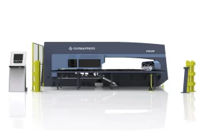
Durmapress specializes in designing, manufacturing, and selling various metal processing equipment, including bending machines, shears, punches, and laser cutting machines. The company was founded in 2014, with years of experience and technology accumulation. DurmaPress has become one of the well-known brands in China's metal processing machinery industry.


Contact Us
Recent Posts


Categories
Follow Us
Weekly New Video
The global demand for high-precision sheet-metal fabrication continues to rise, and manufacturers increasingly rely on advanced press brakes to deliver consistent bending accuracy, faster production cycles, and lower operational costs. But few fabricators truly understand how a press brake is made, what components influence performance, or how modern manufacturing ensures repeatable accuracy.
This guide reveals the complete press brake manufacturing process, the critical components, and how modern CNC and servo technologies elevate machine performance.


1. What Is Press Brake Manufacturing?
Press brake manufacturing refers to the engineering, fabrication, assembly, and quality-control processes involved in building a fully functional bending machine. These steps ensure the press brake achieves:
- High bending accuracy
- Stable long-term performance
- Reliable hydraulic or servo operation
- Efficient CNC automation
→ You may also explore our CNC Press Brake solutions for high-precision bending.
2. Full Manufacturing Process of a Modern Press Brake
Modern press brake production typically includes eight major stages. Each stage influences machine accuracy, reliability, and lifespan.
2.1 Frame Welding & Stress Relief
The frame is the backbone of every press brake. Durmapress uses heavy-duty steel plates, laser-cut and CNC-machined, then welded by certified technicians.
Key steps include:
- CNC plasma or fiber-laser cutting
- Multi-axis robotic welding
- Post-weld stress-relief heat treatment
- Machining of mounting surfaces
A stress-relieved frame prevents deformation over years of bending operations.
2.2 CNC Gantry Milling for Precision Surfaces
After stress relief, the frame undergoes gantry milling to ensure perfect parallelism between the table and ram.Critical tolerances include:
- Table–ram flatness: ≤ 0.02 mm
- Side-frame alignment: ≤ 0.03 mm
- Y1/Y2 cylinder mounting accuracy
This step directly impacts bending precision and machine lifespan.
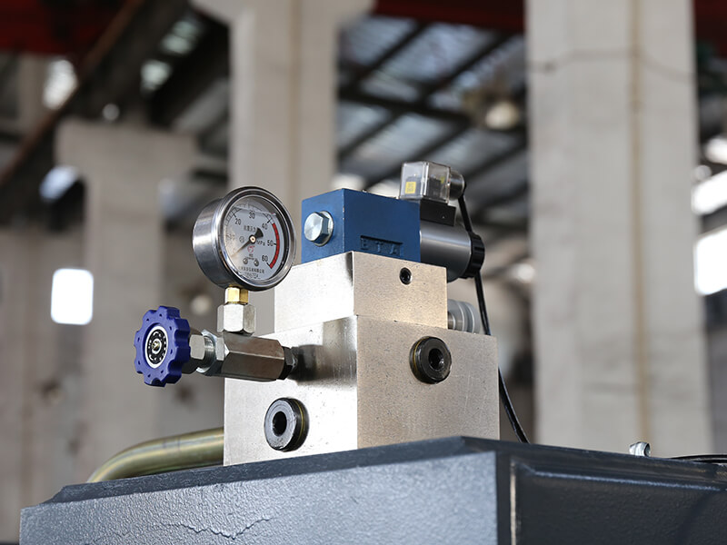
2.3 Hydraulic System Assembly
The hydraulic system controls ram movement. High-quality press brakes typically use:
- Bosch-Rexroth proportional valves
- Sunny / Parker pumps
- High-pressure seamless hydraulic pipes
- Oil cooling systems
Hydraulic calibration ensures:
- Smooth ram movement
- Stable oil temperature
- Reduced noise and wear
2.4 Electrical System Integration
Modern machines include advanced components from:
- Schneider® electrical components
- Delta / Siemens inverters
- High-precision encoders
Proper cable routing and electrical cabinet cooling are crucial for reliability.
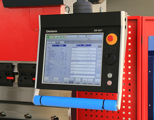
2.5 CNC System Setup & Programming
This is where the machine becomes “smart.”
Common CNC systems include:
- Delem DA-53T / DA-66T / DA-69T
- CybTouch
- ESA S640
- Estun E21 / E300
→View our full range of Sheet Metal Bending Machines for different production requirements.
The CNC system manages:
- Y1/Y2 axis synchronization
- Crowning adjustments
- Backgauge movement
- Bending sequence simulation

2.6 Backgauge Assembly & Calibration
The backgauge ensures repeatable bending.High-end machines use ball screws, linear guides, and servo motors for micron-level positioning.
Common structures:
| Backgauge Type | Axes | Application |
|---|---|---|
| X axis | 1 | Basic bending tasks |
| X + R | 2 | Standard industry use |
| X + R + Z1 + Z2 | 4 | High-mix sheet-metal fabrication |
| 6-axis backgauge | 6 | Complex multi-step productions |
2.7 Tooling, Clamping & Crowning Installation
This step includes:
- Upper punch installation
- Lower die installation
- Fast clamping or Wila-style clamping system
- Mechanical or hydraulic crowning.
→Learn more about our Press Brake Tooling options for different bending applications.
2.8 Final Assembly, Accuracy Testing & Trial Bending
Before delivery, every modern press brake undergoes:
- Bending angle accuracy test
- Repetition test
- Cylinder balance test
- Backgauge repeatability test
- Safety device (DSP / LazerSafe) calibration
Only after passing all testing does the machine enter packaging and shipping.
3. Key Components in Modern Press Brake Manufacturing
Modern press brakes rely on many precision components. Below are the most influential parts.
3.1 Frame & Table
Modern press brakes rely on many precision components. Below are the most influential parts.
3.2 Drive System (Hydraulic or Servo Hybrid)
Servo hybrid technology is becoming the preferred choice thanks to:
- 30–60% lower oil consumption
- Faster ram speeds
- Higher energy efficiency
- Lower noise
→Discover our Servo Hybrid Press Brake series for energy-efficient bending.
3.3 CNC Controller
The CNC system determines the ease of programming and bending simulation accuracy.
3.4 Tooling System
Includes punches, dies, hemming tools, radius tools, and custom profiles.
3.5 Backgauge System
Ensures accurate positioning for every bend.
3.6 Safety Systems
- DSP laser protection
- Light curtain
- Rear safety fences
Essential for CE/ISO compliance.
4. Applications of Modern Press Brakes
Press brakes are used across industries:
- HVAC
- Automotive parts
- Architecture structures
- Electrical enclosures
- Steel furniture
- Transportation equipment
→Explore how a Robotic Press Brake System improves productivity in high-volume automation.
5. Innovations Shaping the Future of Press Brake Manufacturing
Modern factories are adopting:
- Servo hybrid systems
- Automatic tool changers
- Real-time angle measurement systems
- Offline programming software
- Robotic integration
These innovations significantly reduce labor costs and improve consistency.
6. Summary Table: Key Manufacturing Steps & Their Impact
| Manufacturing Stage | What Happens | Impact on Quality |
|---|---|---|
| Frame welding & stress relief | Builds the main structure | Stability & durability |
| Gantry milling | Precision machining | Bending accuracy |
| Hydraulic assembly | Pump, valves, piping | Smooth motion |
| CNC installation | Software intelligence | Automation level |
| Backgauge assembly | Positioning system | Repeatability |
| Tooling & crowning | Punch/die setup | Angle accuracy |
| Final testing | Calibration & bending tests | Overall performance |
FAQs
Typically 20–45 days depending on size, CNC system, customization, and tooling requirements.
Main factors include frame rigidity, CNC synchronization, hydraulic stability, and the type of tooling used.
Hydraulic is durable; hybrid is efficient and stable; servo-electric is ideal for thin materials and high-speed applications.
CE certification, ISO9001, and in some regions, UL compliance for electrical safety.
Yes. Many factories integrate robotic loading/unloading with a robotic press brake cell.