Sobre nós
Durmapress specializes in designing, manufacturing, and selling various metal processing equipment, including bending machines, shears, punches, and laser cutting machines. The company was founded in 2014, with years of experience and technology accumulation. DurmaPress has become one of the well-known brands in China's metal processing machinery industry.


Contate-nos
Publicações recentes

Categorias
Siga-nos
Novo vídeo semanal
Table of Contents
A drawing calls for 100 mm. The part measures 99.85 mm. Pass or fail?
Search for laser cutting accuracy and you will find figures that cannot all be true at once. Some sources publish tolerances measured in thousandths of a millimetre. Others quote a quarter of a millimetre — hundreds of times wider. Both can be technically defensible, because they are describing different things: the beam, the machine, and the finished component.
This guide gives you the working tolerance ranges first, then explains what drives them, how to design parts that hold them, and how to verify them before production.
1. How Accurate Is Laser Cutting?
For planning purposes, laser-cut flat features are typically held within ±0.1 mm to ±0.3 mm. Tolerance sits toward the tighter end on thin, flat material with simple geometry, and widens as thickness, part size and geometric complexity increase.
That range is a planning figure, not a guarantee. Six variables determine where any given job lands within it — or outside it:
- Material type and grade
- Material thickness
- Part size and geometry
- Machine condition and calibration
- Process parameters — power, speed, focal position, assist gas
- How the finished part is measured
The pattern is consistent across the industry: thin, flat, dimensionally stable material with simple geometry holds tight tolerance. Thick plate, long profiles and narrow strips do not.
One distinction matters more than any single number, and it is the reason published figures disagree so wildly: machine accuracy and part accuracy are not the same thing. The next section breaks both down.
2.Laser Cutting Tolerance Chart
2.1 Typical Tolerance by Material Thickness
| Material Thickness | Where It Typically Falls Within the Planning Band |
|---|---|
| ≤ 1 mm | Tighter end of ±0.1 – ±0.3 mm |
| 1 – 3 mm | Tighter end of ±0.1 – ±0.3 mm |
| 3 – 6 mm | Mid band |
| 6 – 10 mm | Mid to wider end |
| 10 – 20 mm | Wider end, and may exceed ±0.3 mm on larger parts |
| > 20 mm | Expect wider than ±0.3 mm; confirm per part |
Important: These are indicative planning ranges, not guaranteed specifications. Actual capability depends on material grade, thickness, part size and geometry, machine configuration, optics and consumable condition, process parameters, and inspection method. They are not a universal industry standard and should not be treated as a contractual figure. Confirm achievable tolerance for your complete process route before production.
2.2 How Part Size Affects Tolerance
Thickness is only half the picture. Tolerance also widens with the nominal dimension being measured.
A 50 mm feature on 2 mm sheet is comfortably inside the tight end of the band. The same 50 mm feature on 20 mm plate sits well above it. Take that plate part out to 1500 mm and the achievable deviation grows again — often by several times the thin-gauge figure.
Two mechanisms drive this:
Thermal behaviour. The metal absorbs heat during cutting and expands. Once the part is cut free and cools, it contracts — frequently finishing slightly smaller than the programmed dimension. Thicker sections absorb and retain more heat, so the effect scales with thickness.
Accumulated travel. A longer contour means the beam travels further and the cut takes longer. That gives positional deviation more distance to accumulate and gives the part more time to move as stress is released.
Neither is a machine defect. Both belong on the drawing rather than in a goods-in dispute.
2.3 Why Published Accuracy Figures Disagree
| What the Figure Describes | Typical Published Magnitude | What It Means for Your Part |
|---|---|---|
| Focused beam diameter | Tens of microns | Determines minimum feature capability, not part tolerance |
| Kerf width | Roughly 0.1 – 0.3 mm | Compensated in CAM; drift here shifts every part uniformly |
| Machine positioning accuracy | Hundredths of a millimetre | Measured on the machine under controlled conditions, not on the part |
| Contracted part tolerance | ±0.1 – ±0.3 mm typical | The only figure that appears on an inspection report |
Some suppliers publish accuracy figures an order of magnitude tighter than others. That gap usually reflects what is being measured, not how good the equipment is.
A beam-level or machine-level number describes controlled conditions with no material, no heat and no stress. A contracted part tolerance accounts for thermal expansion and contraction, residual stress in the sheet, cut-edge taper, part movement after the profile is released, and kerf compensation error.
When you request a quote, ask which one you are being given. The answers are frequently an order of magnitude apart, and only one of them is contractual.
2.4 ISO 9013 and Laser Cut Quality
Dimensional tolerance is only one measure of a cut. Edge quality is governed separately, and there is an international standard for it.
ISO 9013:2017 — Thermal cutting: Classification of thermal cuts, geometrical product specification and quality tolerances — covers thermal cutting processes including laser cutting, and applies to laser cuts in the range of approximately 0.5 mm to 32 mm material thickness.
The standard classifies cut quality using measurable characteristics of the cut face rather than a single pass/fail judgement, and defines quality ranges that can be specified on a drawing or in a purchase agreement.
Two practical points:
- Specify the standard, not an adjective. "Clean edge" is unenforceable. A stated ISO 9013 quality requirement is measurable and mutually understood.
- Verify against the controlled document. Quality class definitions and their permitted values should be read from the current standard itself, not from a summary table. Confirm the edition referenced on your drawing or contract.
Edge quality and dimensional tolerance are specified separately because they fail separately. A part can be dimensionally perfect with an unacceptable cut face, or have an excellent edge while sitting outside its size tolerance.
3. Accuracy, Precision and Tolerance: What's the Difference?
Accuracy is how closely a finished part matches the drawing — a measure of correctness.
Precisão, or repeatability, is how consistent the process is from part to part — a measure of scatter.
Tolerance is the deviation the drawing permits before rejection — a functional and commercial decision, not a machine property.
A machine can be extremely repeatable and still be wrong. Two hundred identical parts, all 0.3 mm undersized, are precise but inaccurate. That is a kerf compensation or calibration fault, and it stays invisible if you only check parts against each other instead of against the drawing.
For buyers, the practical rule: never specify "high precision" in an RFQ. Specify the allowable deviation on the dimensions that actually matter.
3.1 What Is Kerf in Laser Cutting?
Kerf is the width of material the beam removes as it travels.
It is not a fixed property of a machine. Kerf shifts with beam spot size, focal position, power, cutting speed, assist gas type and pressure, material and thickness. A cutting head lens narrows the beam to a small diameter, but the resulting kerf is always wider than the beam itself — and no cut line can ever be narrower than the kerf.
CAM software compensates by offsetting the beam path to one side of the programmed contour, so the finished edge lands on the drawing line rather than half a kerf away from it.
Narrow kerf enables fine detail. It does not produce dimensional accuracy. With kerf compensation set incorrectly, a machine with exceptionally narrow kerf will cut every part out of tolerance — consistently, and in the same direction.
3.2 Machine Accuracy vs Finished Part Accuracy
Machine builders publish positioning accuracy e repeat positioning accuracy — how precisely the motion system places the cutting head at a commanded coordinate. On modern CNC platforms these figures are typically stated in hundredths of a millimetre.
Those numbers are real, and they describe the machine — not your part.
By the time a component has been cut, several effects have been added on top:
- Thermal expansion during cutting and contraction on cooling
- Residual stress released from the sheet as the contour opens
- Cut-edge taper through the material thickness
- Part movement once the external profile is severed
- Kerf compensation error
Finished part tolerance is always wider than positioning accuracy. A machine specified in hundredths of a millimetre routinely produces contracted part tolerances an order of magnitude wider — not because the specification is false, but because the specification never included the material.
This is the single most common misreading in laser cutting procurement. The same distinction applies across sheet metal fabrication, and it is covered in more depth in our sheet metal tolerances guide.
4. What Affects Laser Cutting Accuracy?
Accuracy problems are rarely caused by one thing. They come from two or three variables interacting — a worn nozzle on a stressed sheet running an aggressive parameter set.
4.1 Material Type and Thickness
Identical parameters do not produce identical results across materials.
Mild steel, stainless steel, aluminium, brass and copper differ in reflectivity, thermal conductivity and melting behaviour. Reflective, conductive metals demand different power and gas strategies and conduct heat away from the kerf faster, changing both edge quality and distortion behaviour.
Thickness compounds everything: more energy input, more retained heat, more pronounced edge taper, slower cutting. Most fabrication work sits below 20 mm for this reason; beyond that, achievable tolerance widens significantly and alternative processes often become more sensible.
Incoming material quality matters more than most specifications acknowledge. Mill scale, coatings, surface contamination and grade variation between lots all shift results on an otherwise unchanged machine. Cutting behaviour also varies significantly between material types — what materials a fiber laser can cut explains how those differences carry forward into every downstream dimension.
4.2 Sheet Flatness and Internal Stress
This factor is absent from most published guides and causes a disproportionate share of real rejections.
Sheet is produced as coil, then decoiled and levelled flat. Levelling removes the curvature but not all of the internal stress. When the laser cuts a contour it releases that stress locally, and the material moves. The effect is worst on long, narrow and asymmetric parts — a thin strip can bow measurably the moment its profile completes, even though the beam path was accurate to hundredths of a millimetre.
Flatness also affects focus directly. If material lifts, standoff distance changes, focal position shifts relative to the surface, and kerf width varies along the cut. Support slat condition, clamping and capacitive height control become accuracy factors, not handling details.
4.3 Laser Power, Speed and Focus
Power and speed must be matched to material and thickness. Too much heat for the speed widens the kerf, enlarges the heat-affected zone and encourages dross. Too little energy for the speed produces incomplete cuts and edges too rough to measure reliably.
Focal position is equally critical. Set incorrectly relative to the material surface, it changes the effective spot size at the cut — widening kerf and increasing taper through the thickness.
Maximum power and maximum speed produce maximum throughput, not maximum accuracy. On tight-tolerance work the optimum parameter set is usually a conservative one.
4.4 Optics, Nozzle and Assist Gas
Beam delivery degrades gradually and silently, which is what makes it dangerous.
Dust, spatter or residue on lenses and protective windows scatters the beam and reduces energy density at the focal point. A worn, damaged or off-centre nozzle disrupts the gas stream and skews the cut. Inconsistent gas pressure or contaminated gas changes how molten material clears the kerf.
None of these produce an obvious failure at first. They produce a slow drift in kerf width and edge quality that shows up as parts creeping toward the tolerance limit over weeks.
4.5 Machine Stability and Motion Control
Frame rigidity, vibration damping, guide and drive quality, and encoder feedback all contribute — as does calibration of both the motion axes and the height-sensing system.
Dynamics matter at features, not on straight lines. Acceleration and deceleration around corners, small holes and dense contours is where programmed geometry and actual geometry diverge. It is why sharp corners round off and small features lose definition at high feed rates.
Maintenance is an accuracy issue, not just an uptime issue. Wear in drives, bearings and the cutting head assembly translates directly into dimensional drift.
4.6 Part Size and Shape
Larger outlines accumulate more deviation — both exterior profiles and large internal features. The beam travels further, the cut takes longer, and more heat enters the part.
Narrow strips heat faster and distort more readily. Densely packed contours concentrate thermal load in a small area. Sharp internal corners force direction changes no drive executes perfectly at production speed. Nesting position and cut sequence change a part's thermal history, which is why the same part can measure differently depending on where it sat on the sheet.
5. Fiber vs CO2 Laser: Does Laser Type Affect Accuracy?
Fiber lasers are widely used for precision sheet metal work, particularly on thin to medium gauge and on reflective metals such as aluminium, brass and copper, where the shorter wavelength is absorbed more efficiently. The tightest tolerances in sheet metal work are generally achieved with fiber systems on thinner material.
CO2 lasers remain relevant for non-metals and for certain applications where their beam characteristics suit the job.
Laser type alone does not determine part tolerance. A well-maintained, well-calibrated machine with a disciplined parameter library and a skilled operator will outperform a newer, higher-powered machine running contaminated optics and a generic parameter set. Machine build quality, beam delivery condition, control system, material consistency and operator capability all sit between the laser source and the finished dimension.
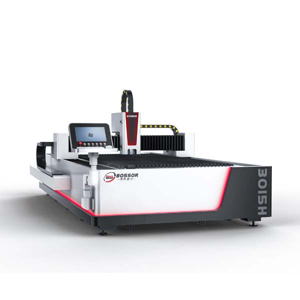
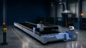
If you are evaluating equipment rather than a service, our fiber laser cutting machine range is configured around this principle — accuracy comes from the complete system, not the source alone.
6. Why Laser Cutting Accuracy Matters
- Assembly fit. Parts landing near nominal go together without adjustment. Parts drifting within tolerance in opposite directions stack into interference.
- Downstream operations. A cutting deviation does not stay a cutting deviation. Bend lines referenced from an inaccurate edge inherit and amplify the error. Weld gaps widen unevenly. Fixtures stop locating correctly. Accuracy degrades as operations accumulate — cut, then formed, then welded, in that order.
- Batch consistency. Prototype approval is meaningless if production parts differ. Repeatability is what makes an approved sample worth anything.
- Reduced secondary work. Correctly set parameters leave minimal burr, often not worth removing — frequently the difference between a competitive quote and an uncompetitive one.
- Lower scrap and predictable cost. Fewer rejects, less remade material, and lead times that hold.
This becomes non-negotiable in automotive, aerospace, electronics enclosures, medical devices, industrial machinery and precision fabrication.
7. Laser Cutting vs Plasma, Waterjet and CNC Machining
| Laser | Plasma | Waterjet | CNC Machining | |
|---|---|---|---|---|
| Dimensional tolerance | Tight | Looser than laser | Comparable to laser | Tightest |
| Repeatability | High | Lower | Comparable to laser | Highest |
| Heat-affected zone | Small | Large | None | None |
| Practical metal thickness | Typically to ~20 mm | Thicker than laser | Very thick possible | Setup dependent |
| Speed | Fastest on thin to medium gauge | Faster on thick plate | Slowest | Slowest per feature |
| Edge finish | Clean, minimal burr | Rougher, dross likely | Matte, no burr | Machined |
| Best fit | Precision sheet metal, complex profiles | Thick plate, loose tolerance | Heat-sensitive or exotic stock | Tight tolerances, 3D features, bores |
Indicative comparison for planning. Actual performance varies by equipment, material and application.
There is no universally superior process — only a correct one for a given tolerance, material, thickness and volume. On precision work the answer is frequently not either/or: laser cut the profile, then machine the critical features.
8. Design Tips for Accurate Laser-Cut Parts
Most tolerance problems are designed in before the file reaches the machine.
- Size holes and slots against material thickness. As a working rule, hole diameter should not be smaller than material thickness, and slot width should be at least equal to it.
- Avoid fragile webs. Narrow connecting sections heat up, distort and sometimes fail during cutting.
- Use internal corner radii. A perfectly sharp internal corner asks the motion system to do something physically impossible at production speed.
- Maintain feature spacing between features, and between features and part edges.
- Manage unsupported areas so material does not distort or drop during cutting.
- Supply clean vector geometry — no duplicate lines, open contours, stray construction geometry or scaling errors. A file error is indistinguishable from a machine error in the finished part.
- Tolerance selectively. Mark critical dimensions; leave everything else at general tolerance. Blanket tight tolerancing is one of the most expensive and most common drawing errors in sheet metal work.
8.1 Small Holes and Narrow Slots
Piercing concentrates a large amount of energy into a very small area before the cut even begins. On a small hole that heat has nowhere to dissipate, producing taper through the thickness, an oversized entry, a rough bore, or an incomplete cut.
Achievable minimum feature size scales with material thickness and machine capability. Treat holes approaching or below material thickness as a process risk requiring verification, not an assumption.
For critical small features — bearing seats, dowel locations, precision fastener holes — cut undersize and finish by machining.
8.2 Cut Order and Heat Control
- Cut internal features before the external profile. Once the outline is severed the part is no longer rigidly located, and any subsequent internal cut inherits that instability.
- Distribute heat across the sheet. Cutting a cluster of adjacent parts consecutively concentrates thermal load; sequencing across the sheet lets heat dissipate.
- Control part release. Micro-joints or tabs keep small parts located until cutting completes, preventing tip-up into the cutting head.
- Place lead-ins deliberately. A lead-in on a critical edge leaves a witness mark exactly where it is least wanted.
9. How to Measure Laser Cutting Accuracy
A tolerance claim that has not been measured is a marketing statement.
9.1 Laser Cutting Accuracy Measurement Methods
| Method | Best For | Limitation |
|---|---|---|
| Vernier / digital caliper | General dimensions, quick shop-floor checks | Operator-dependent; poor on internal features |
| Micrometer | Thickness and tight external dimensions | Limited to accessible surfaces |
| Pin / plug gauges | Fast go/no-go hole verification | Pass-fail only, no measured value |
| Profile projector | Small parts, contours, radii | Size-limited |
| Optical / vision measurement | Multiple features, fast repeat inspection | Requires setup and fixturing |
| CMM | Tight tolerances, full profile verification, formal reports | Slowest, highest cost |
| CAD overlay comparison | Whole-contour conformance | Requires scanning capability |
9.2 Inspection Practice That Works
- Understand what you are checking. Verifying one width tells you almost nothing about profile conformance. Full contour comparison catches accumulation errors that point checks miss entirely.
- Use first article inspection, then sample. Approve a first article before the batch runs, then sample at a defined frequency to catch drift.
- Control measurement conditions. Measure parts fully cooled — a warm part reads oversize. Deburr before measuring critical edges; a burr distorts the reading.
- Define the measurement condition on the drawing. State whether a dimension applies free-standing or restrained, and at which stage of the process route it is verified.
- Document it. For critical components, record instrument, conditions and results. This is what converts a capability claim into a supplier qualification.
10.How to Improve Laser Cutting Accuracy
To improve laser cutting accuracy, check beam alignment, focal position, optics cleanliness, nozzle condition, motion calibration, cutting parameters, sheet flatness and kerf compensation — in that order.
- Verify beam alignment and focal position. Start here; it is the most common root cause.
- Inspect and clean all optics — lenses, protective windows, and mirrors on CO2 systems.
- Check nozzle centring and condition. Replace worn or damaged nozzles rather than nursing them.
- Calibrate the motion system and height control, including capacitive sensor calibration.
- Re-optimise parameters per material — power, speed, frequency, gas type and pressure — validated on the actual material lot rather than a generic library entry.
- Improve sheet support and flatness. Replace burnt slats; check clamping.
- Revise nesting and cut sequence to distribute heat.
- Audit CAM settings and kerf compensation against measured kerf, not assumed kerf.
- Run test cuts and record results. A documented, measured parameter library is what separates shops that hold tolerance from shops that hope to.
11. Common Laser Cutting Accuracy Problems
| Symptom | Most Likely Causes |
|---|---|
| Parts consistently oversized or undersized | Kerf compensation error, calibration, focal position |
| Holes out of tolerance | Piercing heat, focus, small-feature limits |
| Top and bottom dimensions differ | Cut edge taper — focus, power, thickness |
| Results vary across the sheet | Sheet flatness, support condition, thermal buildup |
| Warped or distorted parts | Residual stress, heat concentration, narrow geometry |
| Excessive dross affecting measurement | Gas pressure or purity, speed, nozzle condition |
| Rounded corners, lost detail | Excessive acceleration, feed rate too high at features |
| Accuracy declining over time | Optics contamination, consumable wear, lost calibration |
11.1 Why Are Laser-Cut Parts Oversized or Undersized?
Kerf compensation set incorrectly — the most common cause. If actual kerf has drifted from the CAM value, every part shifts by the same amount in the same direction, which is exactly why the error looks so consistent.
Focal position error changes effective kerf width and therefore the finished dimension.
Parameter mismatch — a set built for one grade or lot applied to another.
Calibration or scaling error — rare, but produces errors that scale with part size, a useful diagnostic signature.
Thermal expansion and contraction. Heat absorbed during cutting expands the metal; the part shrinks as it cools and finishes slightly smaller than the drawing. This is a systematic, correctable error rather than random scatter.
Measurement error. Before chasing a machine fault, confirm the parts were measured cool, deburred, with a calibrated instrument.
11.2 Why Is Accuracy Lower on Thick Plate?
Several effects compound at once. Higher energy input means more heat entering the workpiece and more thermal distortion. The beam changes shape as it travels through greater material depth — the effect is more pronounced in thick sections because of the longer distance travelled — widening the kerf toward the bottom of the cut. Edge taper becomes more pronounced, so top and bottom dimensions diverge. Cutting speed drops, extending heat exposure time. Focal position and gas dynamics become far less forgiving.
The practical response: widen tolerance on thick sections, machine the critical features afterwards, or move the job to a different process.
12. How to Choose a Laser Cutting Machine or Supplier
- Ask for demonstrated part tolerance, not positioning accuracy. A supplier who can only quote the machine specification has not measured their own capability.
- Match capability to your material and thickness. A machine excellent at 2 mm stainless may be marginal at 15 mm carbon steel.
- Ask about batch repeatability. One good part is not a capability.
- Review calibration and maintenance procedures — frequency, records, responsibility. This predicts accuracy six months from now.
- Assess CAM and parameter management. Documented parameter libraries beat operator memory.
- Request samples for critical work, cut in your actual material.
- Confirm inspection capability and whether formal reports can be issued.
- Consider the full process chain. Bending, machining and finishing under one roof removes tolerance stack-up between suppliers.
- Compare total capability, not laser wattage. Power sells machines; process control delivers parts.
To recommend a configuration responsibly, a machine supplier needs the part drawing, material and thickness, part size, required tolerance and production volume. Any accuracy promise offered without that information should be treated cautiously.
12.1 How to Specify Tolerances When Ordering
- Material grade, thickness and condition
- Correctly scaled CAD file plus a dimensioned drawing
- Critical dimensions and mating features clearly identified
- Bilateral or unilateral tolerance stated per feature
- Edge quality requirements stated separately — reference ISO 9013 where applicable
- Burr, flatness and cosmetic requirements listed separately from dimensional tolerance
- Required inspection method and whether a report is needed
- Prototype and production quantities
- The direct question: is your quoted tolerance machine capability or guaranteed part tolerance?
On unilateral limits: where a hole must never fall below size, or a panel must never exceed an opening, say so on the drawing. A programmer can bias a feature within its allowable band — programming a hole slightly oversize so normal variation stays inside the acceptable range — but only if the drawing states which direction is safe.
And leave out tolerances on dimensions that do not affect function. Tightening a tolerance past a certain point changes the required process rather than merely the effort within it, and that is where cost rises sharply.
13.FAQ
Q1:What tolerance can laser cutting hold?
For planning purposes, laser-cut flat features are typically held within ±0.1 mm to ±0.3 mm. The tighter end applies to thin, flat material with simple geometry; tolerance widens as thickness, part size and complexity increase. Confirm achievable values for your specific part before production.
Q2:What is the typical laser cutting tolerance?
±0.1 mm to ±0.3 mm is a realistic planning band for flat sheet metal features. It is an indicative range rather than a guaranteed specification, and it shifts with material, thickness, geometry and inspection method.
Q3:Does laser cutting accuracy change with material thickness?
Yes, significantly. Thicker material absorbs more heat, distorts more, produces more edge taper and cuts more slowly. Achievable tolerance widens steadily from thin sheet through to heavy plate.
Q4: What is the tolerance of fiber laser cutting?
Fiber lasers are commonly used where tight tolerance is needed on thin to medium gauge material, and the tightest sheet metal tolerances are generally achieved on thinner sections. Standard production tolerance is wider than best-case capability — specify which one you need.
Q5:How accurate is a 1 mm laser cut?
Thin material sits at the tighter end of the typical range, because it absorbs less heat and distorts less than thicker sections. Part size still matters — a small bracket and a 2 m panel in the same 1 mm sheet will not hold the same tolerance.
Q6:Is kerf width the same as cutting tolerance?
No. Kerf is the width of material removed; tolerance is the allowable deviation of the finished dimension. Narrow kerf enables fine detail but does not guarantee dimensional accuracy — kerf compensation must be set correctly in CAM.
Q7:Does laser kerf affect dimensional accuracy?
Indirectly. Kerf itself is compensated in programming. But if actual kerf drifts from the programmed value — through focus shift, optics contamination or a parameter change — every part shifts dimensionally in the same direction.
Q8:How small can a laser-cut hole be?
As a working rule, hole diameter should not be smaller than material thickness. Below that, expect taper, oversized entry or incomplete cuts. Critical small holes are usually cut undersize and finished by machining.
Q9:Is laser cutting more accurate than plasma cutting?
Yes. Laser holds substantially tighter tolerance with a cleaner edge and a much smaller heat-affected zone. Plasma remains competitive on thick plate where tolerance requirements are loose and cost per part matters more.
Q10:Is laser cutting more accurate than waterjet cutting?
They are broadly comparable on dimensional tolerance. Waterjet's advantage is zero heat input — no thermal distortion and no metallurgical change. Laser is usually faster on thin to medium gauge metal.
14. Conclusion
Laser cutting holds ±0.1 mm to ±0.3 mm on typical sheet metal work, tightening on thin, simple, flat parts and widening on heavy plate and large geometry.
What moves your job within that band — or outside it — is the combination of material, thickness, part size, machine condition, process control and inspection method. That is why any single universal accuracy figure should be treated as marketing rather than specification.
Three things to carry into your next project:
- Tolerance the features that matter. Leave everything else at general tolerance; blanket precision raises cost without improving the assembly.
- Ask suppliers for measured part capability, not machine specifications. Only one of those appears on an inspection report.
- Verify critical dimensions with a sample cut and documented inspection before committing to production.
If your parts require tight dimensional tolerance or consistent edge quality, DURMAPRESS can review your part drawing and advise on achievable tolerance for your material, thickness, part size and production volume.
Send us your part drawing and tolerance requirements and our engineering team will confirm what is achievable and where the risk sits.