K Factor in Sheet Metal Bending: Chart, Table, Formula & Values
- Conhecimento, Notícias
- 90+ reading now
Sobre nós
Learn what the K factor in sheet metal bending is, how to calculate it, typical values, and how it affects press brake bend allowance and flat pattern accuracy.


Contate-nos
Publicações recentes


Categorias
Siga-nos
Novo vídeo semanal
The K factor in sheet metal bending defines the location of the neutral axis during a bend. It is used to calculate bend allowance, bend deduction, and flat pattern length, which makes it one of the most important values in press brake bending.
This guide provides the K factor formula, a practical chart and reference table, typical values for mild steel, stainless steel, aluminum, and copper, plus a real calculation example to help you choose the right starting value for accurate bending.
What Is the K Factor in Sheet Metal Bending?
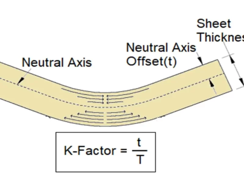
The K factor is a ratio that defines the position of the neutral axis during a bend relative to the material thickness:
Formula:
K = t / T
Where:
- t = distance from the neutral axis to the inner surface of the material
- T = material thickness
Neutral Axis Explained
When sheet metal bends, the inside layer compresses while the outside layer stretches. Between these two zones is the neutral axis, where the material length does not change. The K factor describes the position of this neutral axis within the sheet thickness and directly affects bend allowance, bend deduction, and the final flat pattern length.
Why K Factor Matters in Press Brake Bending
Using the correct K factor is critical for:
Accurate Bend Allowance Calculation
Bend allowance (BA) determines the exact flat length of the sheet before bending.
Using the wrong K factor leads to dimensional errors and costly scrap.
Reducing Trial and Error
Correct K factor reduces repeated test bends in production.
Improves material utilization and lowers scrap rates.
Optimizing CNC Programming
CNC press brakes rely on precise BA and K factor values to produce consistent parts.
The K-factor directly affects bend allowance and therefore changes the final bend deduction formula result.
How to Calculate K Factor and Bend Allowance
K Factor Formula
K = t / T
- Where:
t = distance from the neutral axis to the inner surface - T = material thickness
Bend Allowance Formula
BA = [π × Bend Angle × (R + K × T)] / 180
Where:
BA = Bend Allowance
R = Inside Bend Radius
T = Material Thickness
K = K Factor
Bend Angle = Bend angle in degrees
Example Calculation for Mild Steel
Material: Mild Steel
Thickness (T): 2 mm
Inside Bend Radius (R): 2 mm
Bend Angle: 90°
R/T Ratio: 1.0
Selected K Factor: 0.42
BA = [3.1416 × 90 × (2 + 0.42 × 2)] / 180 = 4.46 mm
This means the sheet needs about 4.46 mm of bend allowance along the bend area to achieve the target flat pattern length. The selected K factor should still be verified with a test bend when tight tolerances are required.
For production bending, a CNC press brake with consistent tooling and controlled setup helps keep the calculated bend allowance closer to the final part dimensions.
K Factor Chart and Table for Sheet Metal Bending
Use the K factor chart below as a starting point when exact shop-tested data is not available. First choose the material, then compare the inside bend radius with the material thickness to get the R/T ratio. Smaller R/T ratios usually require a lower K factor, while larger bend radii generally move the K factor closer to 0.50.
| Material | Condition or R/T Ratio | Recommended K Factor | Notes |
|---|---|---|---|
| Alumínio | R/T < 1.0 | 0.33 | Common starting value for tight bends |
| 1.0 < R/T < 3.0 | 0.40 | Suitable for moderate bend radii | |
| R/T > 3.0 | 0.50 | Neutral axis approaches the center of the material | |
| Mild Steel | R/T < 1.0 | 0.38–0.42 | Verify with test bends for precision parts |
| 1.0 < R/T < 3.0 | 0.42–0.46 | Common range for press brake bending | |
| R/T > 3.0 | 0.50 | Used as a reference for large-radius bends | |
| Aço inoxidável | R/T < 1.0 | 0.40–0.44 | Higher springback requires verification |
| 1.0 < R/T < 3.0 | 0.44–0.48 | Depends on grade, thickness, and tooling | |
| R/T > 3.0 | 0.50 | Large-radius reference value | |
| Soft Copper | Common reference value | 0.35 | Useful starting point for soft copper bending |
| Semi-hard Copper / Brass | Common reference value | 0.41 | Derived from common bend allowance references |
| Hard Copper | Common reference value | 0.45 | Use test bends for final production values |
1.K Factor for Mild Steel
For mild steel, a practical K factor usually falls around 0.38–0.46 for common press brake bending conditions. Tight bends with a small R/T ratio may use a lower value, while larger bend radii can move the K factor closer to 0.50. For accurate production work, verify the selected value with a bend test using the same tooling, thickness, and material grade.
2.K Factor for Stainless Steel
Stainless steel often requires a slightly higher K factor than aluminum because of its higher strength and springback behavior. A common starting range is about 0.40–0.48, depending on the inside bend radius, sheet thickness, grade, and tooling setup. Large-radius bends may approach 0.50.
3.K Factor for Aluminum
Aluminum is often calculated with a K factor around 0.33 for tighter bends, increasing toward 0.40 or 0.50 as the bend radius becomes larger relative to the sheet thickness. Because aluminum grades vary in ductility, test bending is recommended when the flat pattern requires tight dimensional accuracy.
4.K Factor for Copper
For copper, the K factor depends strongly on hardness. Soft copper commonly uses a K factor around 0.35, semi-hard copper or brass may be around 0.41, and hard copper can be closer to 0.45. Use these values as starting points and confirm them with a sample bend when accurate flat patterns are required.
How These K Factor Values Relate to Bend Allowance Formulas
Some CAD and sheet metal references use bend allowance formulas instead of directly listing K factor values. For example, common 90° bend allowance formulas include:
Soft brass or soft copper: BA = (0.55 × T) + (1.57 × R)
Semi-hard copper/brass, soft steel, and aluminum: BA = (0.64 × T) + (1.57 × R)
Bronze, hard copper, cold-rolled steel, and spring steel: BA = (0.71 × T) + (1.57 × R)
For a 90° bend, the standard bend allowance formula can be simplified as:
BA = (1.57 × K × T) + (1.57 × R)
By comparing the two expressions, the K factor can be estimated from the coefficient before T. For example, soft copper uses 1.57 × K = 0.55, so K is approximately 0.35.
| Material Group | K Factor |
|---|---|
| Soft brass / soft copper | 0.35 |
| Semi-hard copper/brass, soft steel, aluminum | 0.41 |
| Bronze, hard copper, cold-rolled steel, spring steel | 0.45 |
These values are useful starting points when shop-tested bend data is not available. For accurate flat patterns, always confirm the final K factor with the same material, thickness, bend radius, and tooling used in production.
Factors Affecting K Factor
The chart above gives practical starting values, but the actual K factor can change in real production. The most important factors are material type, sheet thickness, inside bend radius, tooling, and press brake setup.
Several factors influence the K factor and must be considered during bend calculations:
Material Type
Different metals stretch differently under bending.
Sheet Thickness
Thicker materials shift the neutral axis outward.
Bend Radius
Smaller inside radii increase stretching on the outer fibers.
Tooling & Press Brake Setup
V-die opening and punch radius affect how the sheet bends.
CNC press brake precision also influences the final part.
Best Practices for Accurate Bending
CAD Software Verification
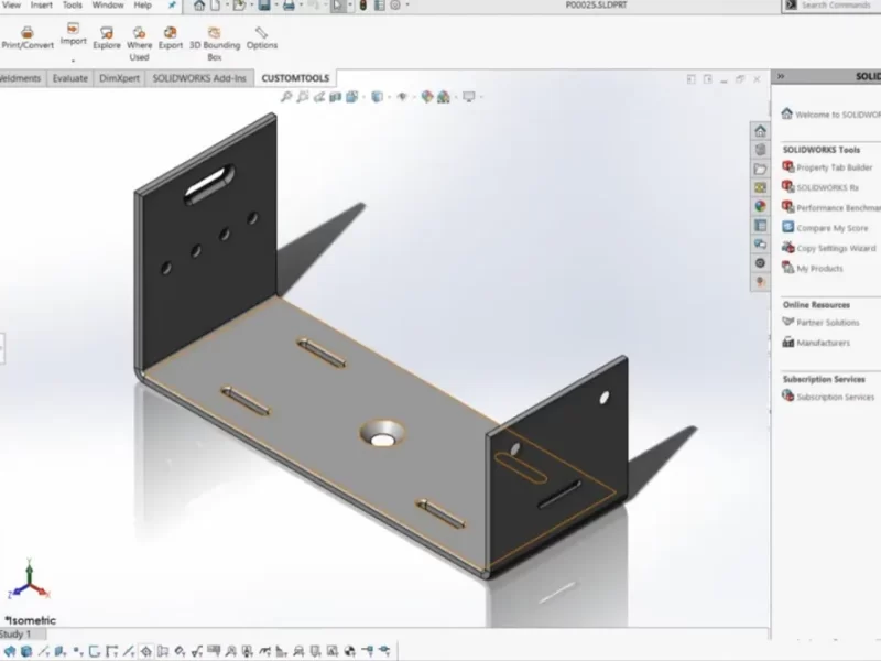
SolidWorks, AutoCAD, and other CAD software can calculate K factor automatically for sheet metal parts.
Default K factor values in software often range 0.33–0.5 depending on material.
Bend Test Method
Bend Test Method
Cut a sample strip from the same material and thickness used in production.
Bend it with the same punch, die, bend radius, and press brake setup.
Measure the final flange lengths and bend allowance.
Compare the measured result with the calculated flat pattern.
Adjust the K factor until the calculated flat length matches the actual bent part.
Check Tooling
Verify punch radius and V-die width for consistency.
Ensure CNC press brake settings match calculated BA.
K Factor vs Bend Allowance vs Bend Deduction
Understanding these related terms helps avoid confusion:
| Term | Meaning | Why It Matters |
|---|---|---|
| K Factor | Neutral axis ratio within the material thickness | Used to calculate bend allowance |
| Bend Allowance | Arc length along the neutral axis | Added to the flat pattern length around the bend |
| Bend Deduction | Amount subtracted from the total outside dimensions | Helps convert formed dimensions into flat length |
Common Mistakes
1.Using the same K factor for all materials
Different materials such as aluminum, mild steel, stainless steel, and copper stretch differently during bending. Do not apply one default value to every material.
2.Ignoring the R/T ratio
The relationship between inside bend radius and material thickness has a direct effect on the K factor. A tight bend and a large-radius bend should not use the same assumption.
3.Ignoring tooling differences
Punch radius, V-die opening, and press brake setup all affect the final bend result.
4.Assuming bend radius without verification
The actual inside radius after bending may differ from the programmed or nominal radius. Measure the bent part when accuracy matters.
Conclusão
The K factor in sheet metal bending is essential for calculating bend allowance and achieving precise, repeatable bends. Using the correct K factor reduces errors, minimizes scrap, and improves manufacturing efficiency. For Prensa dobradeira CNC operations, verifying K factor through CAD or sample testing is highly recommended.
FAQ
Q1: What is the typical K factor for sheet metal?
A typical K factor for sheet metal usually ranges from 0.33 to 0.50. Aluminum may start around 0.33 for tighter bends, mild steel often falls around 0.38–0.46 in common press brake work, stainless steel may range around 0.40–0.48, and large-radius bends can approach 0.50.
Q2: How do you calculate K factor in sheet metal bending?
The K factor is calculated as K = t / T, where t is the distance from the neutral axis to the inner surface and T is the material thickness. In production, the actual value is usually verified by test bending.
Q3: Is K factor always 0.33?
No. 0.33 is a common starting value for some tighter bends, especially in aluminum, but the actual K factor depends on material type, thickness, bend radius, R/T ratio, and tooling.
Q4: What is the K factor for mild steel?
For mild steel, a practical K factor often falls around 0.38–0.46 for common press brake bending. For larger bend radii, the value may move closer to 0.50. Test bending is recommended for accurate flat patterns.
Q5: What is the K factor for copper?
The K factor for copper depends on hardness. Soft copper is commonly estimated around 0.35, semi-hard copper or brass around 0.41, and hard copper around 0.45. These values should be verified with test bends for production accuracy.
Q6: How do I use a K factor chart?
Choose the material first, then calculate the R/T ratio by dividing the inside bend radius by the sheet thickness. Use the matching row in the chart as a starting K factor, then verify it with a test bend if the part requires tight tolerance.
Q7: What affects the K factor in press brake bending?
Material type, sheet thickness, inside bend radius, R/T ratio, tooling, V-die opening, punch radius, and press brake setup can all affect the final K factor.
Q8: How does K factor affect flat pattern calculation?
The K factor determines the bend allowance, which affects the total flat length of the sheet metal part. A wrong K factor can cause the flat pattern to be too long or too short after bending.