What Is Laser Cutting Kerf? Width, Calculation, Compensation & Key Factors
- Conhecimento, Notícias
- 90+ reading now
Durmapress specializes in designing, manufacturing, and selling various metal processing equipment, including bending machines, shears, punches, and laser cutting machines. The company was founded in 2014, with years of experience and technology accumulation. DurmaPress has become one of the well-known brands in China's metal processing machinery industry.


Every time a focused laser beam passes through a workpiece, it removes a thin strip of material. That strip is the kerf — and its width quietly decides whether your finished parts assemble cleanly or end up as scrap. In production fabrication, kerf usually sits between 0.08 mm and 1 mm: small numbers that compound fast. A 0.1 mm kerf deviation repeated across ten mating parts can produce a 1 mm cumulative offset — enough to fail inspection on a tightly toleranced bracket or housing.
The important thing to understand up front is that kerf is not a fixed property of your machine. It shifts with laser type, beam focus, assist gas, focal position, material thickness, and the alloy you're cutting. This guide explains what kerf actually is, how wide to expect it, how to measure and calculate it, when you need to compensate for it in design, and how experienced fabricators hold tighter tolerances.
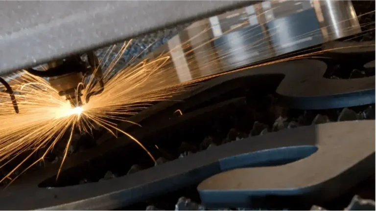
Laser cutting kerf is the total width of material that a laser beam removes as it cuts through a workpiece — measured as the gap between the two cut edges left behind.
It's easy to confuse kerf with beam width, but they are not the same thing:
When the beam contacts mild steel, aluminium, or stainless, it melts and vaporises a sliver of material that the assist gas — oxygen, nitrogen, or compressed air — evacuates from the cut line. The width of that sliver is your kerf.
| Term | What it means |
|---|---|
| Beam / spot size | Diameter of the focused laser at the focal point |
| Kerf width | Total width of material actually removed |
| HAZ (heat-affected zone) | Base metal that stays, but whose microstructure changed from heat |
| Taper | The kerf being wider at the top than the bottom of the cut |
For a deeper look at how kerf ties into overall accuracy, see our guide on standard laser cutting tolerances.
Understanding kerf matters because it directly affects three things every fabricator cares about: the dimensional accuracy of finished parts, nesting efficiency on the sheet, and the cumulative tolerance stack across a multi-part assembly.
Ignore kerf in your CAD files and parts come off the table slightly undersized — usually by half the kerf width on each cut edge. Compensate for it correctly and you'll hit drawing dimensions consistently across the run.
The stack-up problem bites hardest. Industries such as aerospace, medical devices, electronics enclosures, and architectural metalwork treat kerf as a hard design input, not a cutting afterthought. In these sectors, hole diameters, slot widths, tab-and-slot joinery, and press-fit features all depend on kerf-compensated geometry to function.
When kerf isn't accounted for, you'll usually see three downstream problems:
There's also a quieter cost — time spent filing parts to fit or shimming joints is time the machine isn't earning.
Typical laser cutting kerf measures between 0.08 mm and 1 mm, with the exact value driven by laser source, material, thickness, and machine setup.
Fiber lasers generally produce a narrower kerf than CO₂ at the same power class because the 1.06 µm fiber wavelength focuses to a smaller spot than the 10.6 µm CO₂ wavelength. That said, fiber isn't always narrower — the final result still depends on material, thickness, focus, speed, and gas.
| Process & material | Typical kerf (reference) |
|---|---|
| Fiber, thin sheet (0.5–3 mm steel/stainless) | 0.10–0.25 mm |
| Fiber, medium plate (4–12 mm carbon steel) | 0.25–0.50 mm |
| CO₂, thin–medium sheet (1–6 mm steel) | 0.25–0.40 mm |
| High-power fiber, thick plate (15–25 mm, 6–12 kW) | 0.60–1.00 mm |
| Material | Espessura | Average kerf (starting point) |
|---|---|---|
| Acrylic | 1–3 mm | ~0.18 mm |
| Acrylic | 5–8 mm | ~0.21 mm |
| Acrylic | 10–15 mm | ~0.30 mm |
| Birch plywood | 3 mm | ~0.20 mm |
| Birch plywood | 12 mm | ~0.30 mm |
| MDF | 3–12 mm | 0.16–0.28 mm |
| Greyboard | 1200–2400 µm | 0.08–0.12 mm |
| Paper | 90–350 gsm | ~0.08 mm |
Kerf width is set by a combination of physical and technical factors. No single dial controls it.
This is where most dimensional errors start, so it's worth separating four terms that people often blur together:
| Term | Meaning |
|---|---|
| Kerf width | Total material removed by the cut |
| Kerf allowance | Dimension you reserve in design for that material loss |
| Kerf offset / compensation | Shifting the cut path (or geometry) so the finished part hits nominal size |
| Fit clearance | Extra gap between two parts so they actually assemble |
Kerf offset is the adjustment applied to the laser's path so the beam cuts wider than the nominal line by exactly half the kerf on each side — keeping the part at its designed dimensions. On most professional machines, this happens in the CAM software or controller.
Critically, compensation direction depends on geometry:
Avoid double compensation: If your fabricator already offsets kerf at the machine, do not also compensate in your CAD file — you'll end up with holes and slots that are the wrong size.
You can't compensate accurately for a number you haven't measured on your own machine and material.
If you cut a hole of size A and a matching part of size B, the single-side gap is:
Single-side gap = A − B 2
Example: hole = 10 mm, part = 9 mm → (10 − 9) / 2 = 0.5 mm.
Accuracy caveat: This gives you a single-side allowance for fit — it is not identical to the machine's true total kerf in every case. To measure real kerf, use a calibrated test pattern with known cut geometry.
In LightBurn, kerf offset is applied per-shape, not globally:
Even with a good baseline, kerf drifts. Watch these:
Higher power and a defocused beam both widen the kerf. Keep the focal position matched to material thickness.
Gas pressure, nozzle diameter, nozzle height, and cutting speed all move kerf and edge quality together. A worn or contaminated nozzle is a common, overlooked cause of inconsistent kerf.
Tapered kerf — where the cut is wider at the top than the bottom — is one of the most common precision problems, especially on thicker plate.
Common causes:
Remedies:
As a rule of thumb from experience, most materials taper roughly 0.001″ (0.025 mm) for every 0.1″ (2.54 mm) of thickness — plan for it on thick plate.
Expertise signal:Shops that bake this into the CAD-to-CAM workflow, verify with a first-article cut, and then trust the process stop paying for kerf on every single job.
Kerf is a process result, not a fixed machine constant. Kerf width, allowance, compensation, and fit clearance are different concepts, and the most reliable kerf value always comes from a representative test cut on your own material and machine. Get it right early — through good design rules, calibrated settings, correct offset direction, and first-article inspection — and you'll plan for kerf instead of reacting to it.
Have a design ready? Get an instant laser cutting quote and our team will handle kerf compensation for you.
Kerf refers to the width of material that the laser beam removes as it cuts through a workpiece — the gap left between the two cut edges. In laser cutting it typically ranges from 0.08 mm to 1 mm, depending on the laser, material, and thickness.
Kerf offset is the adjustment that shifts the laser's cutting path so the finished part matches its designed dimensions. The beam is offset by about half the kerf width — outward on outer profiles and inward on holes — so material loss doesn't leave parts undersized.
The most reliable method is a calibrated test cut: cut a known pattern in your exact material and settings, then measure the actual cut features against the design with calipers or a micrometer. For precision work, measure both the top and bottom of the cut to capture taper.
Plan for roughly 0.1–0.25 mm per side on fiber-cut sheet metal as a starting point. Overall kerf runs 0.08–1 mm across processes and materials — narrower on thin fiber-cut sheet, wider on thick plate or flammable materials like wood.
For a hole (A) and matching part (B), the single-side allowance is (A − B) ÷ 2 — for example, a 10 mm hole and 9 mm part give 0.5 mm. Note this describes fit clearance; true kerf width is best confirmed with a calibrated test cut.
In LightBurn, use the Offset Shapes tool or the kerf offset field on the cut layer, and enter half your measured kerf. Offset outward for outer contours and inward for internal cutouts, then run a scrap test cut to verify before running the full job.
Preencha as informações abaixo para receber um orçamento gratuito e uma brochura do produto. Responderemos dentro de 24 horas!