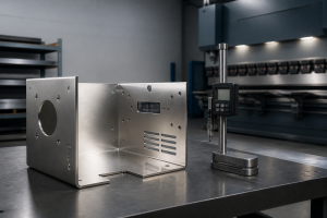
Minimum Bend Radius for Sheet Metal: Chart, Formula & Design Guide
- Conhecimento, Notícias
- 90+ reading now
Learn the minimum bend radius for sheet metal with charts, formulas, and engineering tips. Avoid cracking and improve bending accuracy in press brake operations.


When designing sheet metal parts, one of the most important parameters engineers must consider is the minimum bend radius. Choosing the correct bend radius ensures that the material can be formed without cracking, tearing, or losing dimensional accuracy.
In sheet metal fabrication, the bend radius determines how sharply a sheet can be bent during the press brake bending process. If the radius is too small, the outer surface of the material may stretch beyond its limit and fail.
This guide explains minimum bend radius for sheet metal, including calculation methods, reference charts for different materials, and practical engineering tips used in real manufacturing environments.

The minimum bend radius is the smallest inside radius that can be applied to a sheet metal part without causing material failure on the outer surface of the bend.
In sheet metal fabrication, the bend radius refers to the inside curve of a bend — the distance from the bend's inner surface to the center of curvature. When a sheet is bent, the outer surface stretches while the inner surface compresses. If the bend radius is too small, the outer fibers exceed their elongation limit and crack.
Selecting the correct minimum bend radius is a critical design parameter in any press brake bending operation. It directly affects part quality, tooling selection, and production consistency.
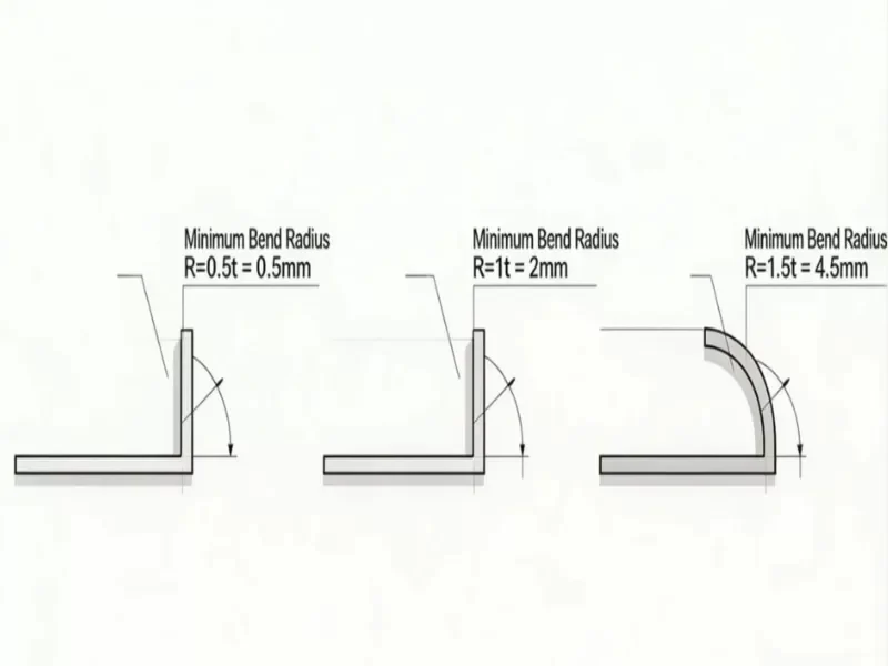
The following sheet metal bending radius chart in mm shows typical minimum inside bend radius values for common materials used in press brake bending.
| Material | Espessura | Minimum Inside Bend Radius |
|---|---|---|
| Mild Steel | 1 mm | 1 mm |
| Mild Steel | 2 mm | 2 mm |
| Mild Steel | 3 mm | 3 mm |
| Mild Steel | 4 mm | 4 mm |
| Mild Steel | 6 mm | 6 mm |
| Aço inoxidável | 1 mm | 1.5 mm |
| Aço inoxidável | 2 mm | 3 mm |
| Aço inoxidável | 3 mm | 4.5 mm |
| Aço inoxidável | 4 mm | 6 mm |
| Aluminum 5052 | 1 mm | 0.8 mm |
| Aluminum 5052 | 2 mm | 1.6 mm |
| Aluminum 5052 | 3 mm | 2.4 mm |
| Aluminum 6061 | 1 mm | 1.5 mm |
| Aluminum 6061 | 2 mm | 3 mm |
The selected V-die opening directly affects the inside bend radius produced during air bending. A common rule is that the inside radius is approximately V-opening divided by 6.
| Material Thickness | Recommended V-Die Opening | Approximate Inside Radius |
|---|---|---|
| 1 mm | 6–8 mm | 1–1.3 mm |
| 2 mm | 12–16 mm | 2–2.7 mm |
| 3 mm | 18–24 mm | 3–4 mm |
| 4 mm | 24–32 mm | 4–5.3 mm |
| 6 mm | 36–48 mm | 6–8 mm |
Below is a commonly used minimum bend radius chart for different sheet metal materials. The values are expressed as multiples of the material thickness.
| Material | Minimum Bend Radius |
|---|---|
| Mild Steel | 1 × thickness |
| Aço inoxidável | 1.5 × thickness |
| Aluminum 5052 | 0.8 × thickness |
| Aluminum 6061 | 1.5 × thickness |
| Cobre | 1 × thickness |
| Latão | 1 – 1.5 × thickness |
| Galvanized Steel | 1 × thickness |
Example:
If a 2 mm stainless steel sheet is being bent:
Minimum radius ≈1.5 × 2 mm = 3 mm
This chart provides a general guideline for air bending on a press brake. Actual results may vary depending on tooling and machine setup.Engineers often use a press brake tonnage chart together with bend radius guidelines to determine the correct machine capacity for bending operations.
Engineers often estimate the minimum bend radius using a simple rule of thumb.In addition to bend radius calculations, engineers also use the bend allowance formula to determine the correct flat pattern length for sheet metal parts.
Where:
| Variable | Meaning |
|---|---|
| k | material factor |
| t | sheet thickness |
Typical values for k:
| Material | k Factor |
|---|---|
| Mild Steel | 1 |
| Aço inoxidável | 1.5 |
| Aluminum 5052 | 0.8 |
| Aluminum 6061 | 1.5 |
Example calculation:
Material: Mild steel
Thickness: 3 mm
You can estimate the minimum bend radius using:
Minimum Bend Radius = k × Material Thickness
Enter:
- Material thickness
- Material factor (k)
The result gives a recommended starting bend radius before production testing.
Several variables influence how tightly sheet metal can be bent.
Different metals have different levels of ductility.
| Material | Ductility |
|---|---|
| Alumínio | High |
| Mild Steel | Medium |
| Aço inoxidável | Lower |
Materials with higher ductility can tolerate smaller bend radii.
As sheet thickness increases, the required minimum bend radius also increases. Thicker sheets experience greater stress during bending.
Sheet metal is produced through a rolling process, which creates a grain structure within the material.
If bending occurs parallel to the grain direction, the risk of cracking increases.
Safer practice:
This allows the metal to stretch more evenly.
The punch radius and V-die opening strongly affect the actual bend radius produced during bending.
A common rule used in sheet metal fabrication:
Example:
| V-Die Opening | Approx. Radius |
|---|---|
| 24 mm | 4 mm |
| 30 mm | 5 mm |
| 36 mm | 6 mm |
Selecting the proper tooling is essential for achieving the desired bend geometry.Modern CNC press brake machines allow operators to precisely control bending force, angle, and tooling alignment.
Understanding the correct bend radius is critical for both design engineers and manufacturing engineers.
When the bend radius is smaller than the recommended value, the outer fibers of the metal may exceed their elongation limit. This is especially common with brittle materials such as stainless steel.
Using a proper bend radius improves dimensional stability and reduces the risk of deformation during bending.
It also helps minimize issues such as:
Extremely small bend radii can increase forming pressure and cause excessive stress on tooling. This may lead to premature wear of punches and dies used in press brake operations.
Another important factor in sheet metal bending is springback.
After the bending force is removed, the material tends to partially return to its original shape. This effect depends on material strength and elasticity.
Typical springback behavior:
| Material | Springback Level |
|---|---|
| Alumínio | High |
| Aço inoxidável | Medium |
| Mild Steel | Low |
Designers often compensate for springback by slightly overbending the part during the press brake process.To compensate for springback, engineers often adjust parameters such as the K factor in sheet metal bending during the design stage.
To achieve reliable bending results, engineers should follow these best practices:
These practices help ensure consistent bending quality and reduce manufacturing defects.
| Problem | Cause | Result |
|---|---|---|
| Cracking on outer surface | Bend radius below minimum | Rejected parts |
| Surface marks | Tooling radius too small | Poor surface finish |
| Springback variation | Radius not matched to material | Inconsistent angles |
| Inaccurate flat pattern | Wrong radius in calculation | Dimensional errors |
For production bending operations requiring precise radius control, CNC press brakes offer programmable control over bending force, stroke depth, and back gauge positioning. This ensures consistent inside bend radius across high-volume runs. Learn more about [Durmapress CNC Press Brake machines] and how they support accurate sheet metal forming.
The minimum bend radius for sheet metal is a critical parameter in both design and manufacturing. Choosing the correct bend radius helps prevent cracking, improves dimensional accuracy, and ensures reliable press brake operation.
By understanding material properties, thickness effects, and tooling influence, engineers can design sheet metal parts that are both functional and manufacturable.
Using a minimum bend radius chart combined with proper engineering guidelines allows manufacturers to achieve consistent bending results across a wide range of materials.
The minimum bend radius for sheet metal is the smallest inside radius that can be applied to a sheet metal part without causing cracking, tearing, or loss of dimensional accuracy.
The actual minimum bend radius depends on several factors, including material type, sheet thickness, grain direction, and bending method. As a general guideline, mild steel often uses a bend radius close to the material thickness (1T), while stainless steel usually requires a larger radius due to its lower ductility.
For accurate results, engineers should refer to material-specific bend radius charts and verify the value based on tooling conditions.
The bend radius of 3mm sheet metal depends on the material and bending process.
As a general reference:
| Material | Typical Minimum Bend Radius |
|---|---|
| Mild Steel | About 3 mm (1 × thickness) |
| Aço inoxidável | About 4.5 mm (1.5 × thickness) |
| Aluminum 5052 | About 2.4 mm (0.8 × thickness) |
These values are starting points for air bending. The actual inside bend radius may vary depending on V-die opening, punch radius, material temper, and grain direction.
Stainless steel typically requires a larger minimum bend radius compared with mild steel because it has lower ductility and higher resistance to deformation.
A common guideline is:
Minimum Bend Radius ≈ 1.5 × Material Thickness
For example, a 2 mm stainless steel sheet generally requires a minimum inside bend radius of approximately:
1.5 × 2 mm = 3 mm
However, the exact value depends on the stainless steel grade, temper, tooling setup, and bending direction.
For Aluminum 5052 H32, the minimum bend radius is typically smaller than stainless steel because of its good ductility.
A common guideline is:
Minimum Bend Radius ≈ 0.8 × Material Thickness
For example:
The actual bend radius may vary depending on the material condition, grain direction, and forming method.
Yes. Sheet thickness has a direct impact on the required bend radius.
As material thickness increases, more stress is generated during bending. Thicker sheets usually require a larger inside bend radius to prevent cracking and maintain dimensional accuracy.
For example, a 6 mm steel plate generally requires a larger bend radius than a 1 mm sheet of the same material.
A common rule-of-thumb formula for estimating minimum bend radius is:
Minimum Bend Radius = k × Material Thickness
Where:
Typical values:
| Material | k Factor |
|---|---|
| Mild Steel | 1 |
| Aço inoxidável | 1.5 |
| Aluminum 5052 | 0.8 |
| Aluminum 6061 | 1.5 |
Example:
For 3 mm mild steel:
Minimum Bend Radius = 1 × 3 mm = 3 mm
If the bend radius is smaller than the recommended value, several problems may occur:
Using the correct bend radius helps maintain part quality and prevents unnecessary tooling stress during press brake operations.
The bend radius of 6mm sheet steel depends on the steel grade, tooling, and bending method.
For mild steel, a common starting point is:
Minimum Bend Radius ≈ 1 × Material Thickness
Therefore:
6 mm steel × 1 = approximately 6 mm minimum bend radius
However, some tooling setups may produce different results. Engineers should confirm the actual radius based on V-die opening and production requirements.
The minimum bend radius for 1mm sheet metal depends on the material:
- Mild steel: about 1 mm
- Stainless steel: about 1.5 mm
- Aluminum 5052: about 0.8 mm
Actual values may vary depending on material temper, grain direction, and tooling selection.
A larger V-die opening produces a larger inside bend radius.
A common air bending rule is:
Inside Bend Radius ≈ V-die Opening ÷ 6
For example:
A 24 mm V-die opening produces approximately a 4 mm inside radius.
The chart above provides typical minimum inside bend radius values in millimeters for mild steel, stainless steel, Aluminum 5052, Aluminum 6061, copper, brass, and galvanized steel. These values are commonly used as starting guidelines for press brake air bending.
Preencha as informações abaixo para receber um orçamento gratuito e uma brochura do produto. Responderemos dentro de 24 horas!