1. What Is Press Brake Tooling?
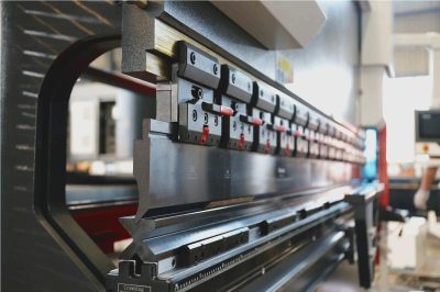
Press brake tooling refers to the punches and dies installed on the upper and lower beam of a press brake to bend sheet metal into specific angles or shapes.
The two core components work together in every bending cycle:
Punch — the upper tool mounted on the ram. It moves downward to press the sheet metal into the die and defines the bend angle at the tip.
Die — the lower tool mounted on the worktable. Its V-opening width controls the bending force required and directly affects the inside bend radius of the finished part.
Beyond punches and dies, a complete tooling setup also includes:
- Tool holders and clamping systems — secure the punch and die in correct alignment
- Crowning compensation tools — correct beam deflection across long bending lengths
- Tooling accessories — radius inserts, hemming tools, and offset adapters for specific forming needs
Tooling quality directly influences:
- Minimum bend radius achievable
- Inside angle accuracy and consistency
- Springback behavior
- Tool wear rate and service life
- Maximum production throughput
A standard toolset includes:
- Punch – downward forming tool
- Die – V-block or specialized lower tool
- Tool holders / Clamping system
- Crowns / crowning system compensation tools
- Tooling accessories (radius inserts, hemming tools, gooseneck tools)
Tooling quality directly influences:
- Minimum bend radius
- Inside angle accuracy
- Springback control
- Tool life and surface wear
- Maximum achievable throughput
2. How to Select Press Brake Tooling
Selecting the wrong tooling is one of the most common causes of angle inconsistency, surface damage, and excessive springback in sheet metal bending. The right choice depends on six key factors:
2.1 Material Type
Different materials require different tooling hardness and V-opening ratios:
- Mild steel — standard 42CrMo tooling is sufficient; V-opening = 8× sheet thickness
- Stainless steel — requires hardened tool steel (minimum 50 HRC) due to higher tensile strength; V-opening = 10× sheet thickness
- Aluminum — softer material, use radius punches to avoid surface marking; V-opening = 12× sheet thickness
Using tooling that is too soft for the material leads to accelerated die wear and angle deviation over time.
2.2 Sheet Thickness
Thickness determines the required V-opening size directly. As a general rule, thicker material requires a wider V-opening to reduce tonnage and avoid cracking at the bend line. See Section 7 for the full V-opening reference table.
2.3 Required Bend Angle
- 90° standard bends — straight punch or gooseneck punch
- Acute angles below 60° — dedicated acute angle punch required; standard punches cannot reach the final angle without damaging the die
- Closed hems — hemming punch and flat die; two-stage process
- Large radius bends — radius punch to form a smooth curve without crease marks
2.4 Part Geometry and Flange Length
Box and tray shapes with tall side flanges require a gooseneck punch to avoid the punch body colliding with the already-formed walls during bending. Always check the clearance between the punch profile and the finished part before setup.
2.5 Production Volume and Change Frequency
- High-mix, low-volume — European segmented tooling allows fast reconfiguration for different part lengths
- Long straight bends, high volume — American one-piece tooling offers higher rigidity and lower tooling cost per meter
- Automated or robotic bending cells — WILA/Trumpf precision tooling with hydraulic quick-change clamping reduces setup time by up to 60%
2.6 Machine Compatibility
Tooling must match the clamping interface of your press brake. European, American, and WILA systems use different tang dimensions and slot geometries and are not interchangeable without adapters. See Section 3 for full compatibility details.
3. Tooling Standards & Compatibility
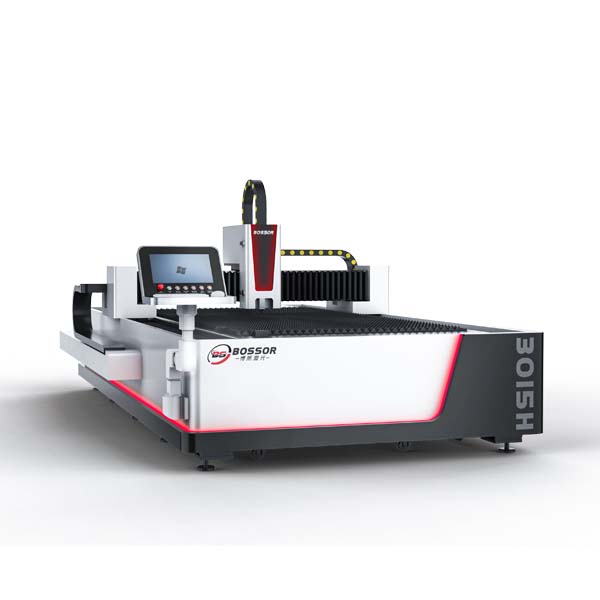
Press brake tooling systems follow several international standards, each optimized for different levels of precision, flexibility, and production requirements. Understanding these standards is essential for ensuring compatibility with your press brake and long-term tooling strategy.To select compatible tooling and clamping systems, refer to our comparison of metal processing machines commonly used in fabrication workshops.
3.1 European Type Tooling (Euro / Promecam Style)
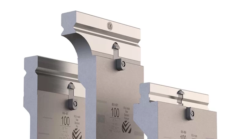
European tooling is the most widely used system in modern CNC press brakes. The punch tang is 13 mm wide with a rectangular slot on the operator-facing side, which engages with the clamping receiver on the press brake ram.
Key characteristics:
- Segmented tool sections (typically 100–835 mm lengths) allow flexible length combinations
- High compatibility with WILA and Trumpf-style clamping systems
- Fast tooling changes without special fixtures
- Precision-ground versions available for high-repeatability applications
Best for: Job shops, high-mix/low-volume production, and any CNC press brake requiring frequent tooling reconfiguration.
3.2 American Type Tooling
American tooling uses a self-locating slot system where punches align automatically when loaded, without requiring manual adjustment. Tools are typically supplied as longer one-piece sections rather than short segments.
Key characteristics:
- High rigidity from one-piece construction
- Safety hooks assist with vertical loading and unloading of heavy tools
- Lower tooling cost per meter compared to European segmented tools
- Less flexible — changing bend length requires cutting or replacing the full tool section
Best for: Heavy-duty bending, long straight bends, and cost-sensitive production environments with low tooling change frequency.
3.3 WILA / Trumpf Precision Tooling
WILA and Trumpf precision tooling represents the highest-specification system available for CNC press brakes. The punch tang is 20 mm wide with slots at both the front and back, held by one or two locking mechanisms.
Key characteristics:
- Ground tolerance typically ±0.01 mm for highly consistent angle output
- Hydraulic or mechanical quick-release clamping reduces tool change time significantly
- Designed for robotic bending cells and automated production lines
- Long service life with minimal wear under high-cycle conditions
Best for: High-volume production lines, aerospace-grade precision requirements, and automated bending systems.
4. Press Brake Tooling Types
4.1 Press Brake Die Types
The punch is the upper tool that makes direct contact with the sheet metal during bending. Punch selection determines the achievable bend angle, minimum flange length, and whether the punch body will interfere with already-formed features on the part. The following are the most common punch types used in industrial press brake operations.
4.1.1 Standard Straight Punch
The standard straight punch is the most widely used punch type in press brake operations. It has a straight body with a pointed or slightly radiused tip, typically available in 85°, 88°, or 90° included angles.
Tip radius options:
- 0.2 mm — for tight bend radius on thin sheet
- 0.6 mm — general purpose, most common
- 1.0 mm and above — for softer materials like aluminum to prevent surface marking
Suitable for:
- Standard 90° bends on flat sheet
- Air bending and bottoming operations
- Mild steel, stainless steel, and aluminum in standard thicknesses
Not suitable for: Parts with tall side walls where the punch body would collide with the already-formed flange.
4.1.2 Gooseneck Punch
The gooseneck punch has a curved, offset body that creates clearance between the punch shank and the workpiece. This allows the punch to complete a bend without the punch body contacting flanges or walls that were formed in a previous bending step.
Key dimensions to check before use:
- Throat depth — must exceed the height of the existing flange
- Tip angle — typically 85° or 88° for standard box bending
Suitable for:
- Box and tray fabrication with four or more bends
- U-channel profiles
- Any part where the punch would otherwise collide with a previously bent flange
Important: Always verify clearance between the gooseneck profile and the tallest formed wall before starting production. Interference during the stroke can damage both the tool and the part.
4.1.3 Acute Angle Punch
Acute angle punches have a tip angle below 60°, typically 30° or 45°. They are used when the finished bend angle is sharper than what a standard punch can achieve without bottoming into the die.
How it works: In air bending, the punch tip angle must be smaller than the target bend angle to allow springback compensation. For bends below 30°, a dedicated acute punch is the only practical option.
Common tip angles: 30°, 45°
Suitable for:
- Acute bends below 60° on finished parts
- Locking seam profiles
- Architectural trim with sharp return angles
Note: Acute punches apply concentrated force on a very narrow contact area. Always verify that the tonnage does not exceed the tool's rated capacity per meter, especially on thicker material.
4.1.4 Hemming Punch
A hemming punch is used in a two-stage process to create a closed hem — a folded edge where the sheet is bent back flat against itself. The first stage uses a standard punch to pre-bend the edge to approximately 30°. The second stage uses the flat face of the hemming punch to press the fold completely closed.
Two-stage process:
- Pre-bend to 30° using a standard acute punch
- Place the pre-bent flange flat on the die, press closed with hemming punch flat face
Suitable for:
- Safety edges on sheet metal enclosures
- Appliance panels and door edges
- Any application requiring a smooth, rounded closed edge
4.1.5 Radius Punch
A radius punch has a curved tip profile instead of a sharp point. Rather than forming a creased bend, it produces a smooth arc across the bend zone, distributing the deformation over a larger area.
Tip radius options: Typically R3, R5, R8, R10, R15 mm — must be specified based on the target inside bend radius of the part.
Suitable for:
- Architectural and decorative sheet metal with visible rounded profiles
- Aluminum and soft materials where crease marks are unacceptable
- Parts requiring a specific inside radius for structural or aesthetic reasons
Selection rule: The punch tip radius should equal or be slightly smaller than the target inside bend radius on the finished part. Using a radius punch that is too large will result in a flatter arc than specified.
4.1.6 Swan Neck / Offset Punch
The swan neck punch (also called offset punch) has an S-shaped or stepped body profile. It is designed specifically for forming Z-shaped or step offset profiles in a single setup, where the punch must reach past one formed flange to press down on the adjacent flat section.
Suitable for:
- Z-bend and step offset profiles
- Panel stiffening ribs
- Parts requiring a parallel offset between two flat sections
Note: Swan neck punches are available in fixed offset dimensions. Always confirm the required step height and flange clearance match the punch geometry before ordering.
Press brake punches play a key role in determining bend shape and clearance conditions. Different punch profiles are used for different forming scenarios.
Learn more about press brake punch types.
4.2 Press Brake Die Types
The die is the lower tool that supports the sheet metal during bending. Die selection — particularly the V-opening width and die angle — directly controls the bending force required, the minimum inside bend radius, and the risk of material cracking. The following are the primary die types used across industrial fabrication environments.
4.2.1 Standard V-Die
The standard V-die is the most commonly used die in press brake operations. It has a single V-shaped groove machined to a specific opening width and included angle. The sheet metal is placed across the die, and the punch presses it down into the V to form the bend.
Key parameters of a V-die:
V-opening width (V): The distance between the two contact edges of the die. This is the single most important dimension to get right — it controls the bending force, the inside bend radius, and springback behavior. General selection rule:
- Mild steel: V = 8 × sheet thickness
- Stainless steel: V = 10 × sheet thickness
- Aluminum: V = 12 × sheet thickness
Die angle: The included angle of the V-groove. Common options are 30°, 60°, 86°, and 88°. For air bending to 90°, an 86° or 88° die is standard. For acute bends, use a die with a matching or smaller angle than the target bend.
Die height: Must be compatible with the press brake's open height and the punch length. Always verify total tooling stack height fits within the machine's stroke range.
Suitable for: The majority of standard bending operations across all material types and thicknesses.
4.2.2 Multi-V Die (2V and 4V)
A multi-V die incorporates two or four V-grooves of different widths on the same die body. The operator rotates or flips the die to switch between V-openings without removing the tooling from the machine.
2V Die: Two V-grooves, typically on opposite faces. Common combinations: 8 mm + 16 mm, or 12 mm + 25 mm.
4V Die: Four V-grooves on four faces of a square die body. Allows four different opening widths in a single tool.
Преимущество: Eliminates the need to change dies when switching between material thicknesses during the same production run, reducing setup time significantly.
Suitable for:
- Job shops running multiple material thicknesses in the same shift
- Operations with limited tooling storage space
- Prototyping and short-run work where flexibility matters more than optimized die geometry
Limitation: Because the die body must accommodate multiple grooves, the height and rigidity of each individual V are slightly lower than a dedicated single-V die. Not recommended for high-tonnage applications.
4.2.3 Rolla V Die
A multi-V die incorporates two or four V-grooves of different widths on the same die body. The operator rotates or flips the die to switch between V-openings without removing the tooling from the machine.
2V Die: Two V-grooves, typically on opposite faces. Common combinations: 8 mm + 16 mm, or 12 mm + 25 mm.
4V Die: Four V-grooves on four faces of a square die body. Allows four different opening widths in a single tool.
Преимущество: Eliminates the need to change dies when switching between material thicknesses during the same production run, reducing setup time significantly.
Suitable for:
- Job shops running multiple material thicknesses in the same shift
- Operations with limited tooling storage space
- Prototyping and short-run work where flexibility matters more than optimized die geometry
Limitation: Because the die body must accommodate multiple grooves, the height and rigidity of each individual V are slightly lower than a dedicated single-V die. Not recommended for high-tonnage applications.
4.2.4 Z-Bend / Offset Die
A Z-bend die (also called offset die) is a matched punch-and-die set specifically designed to form a Z-shaped step offset in a single press stroke. Unlike standard V-dies which require two separate bends to create a step, the offset die completes the entire profile in one operation.
Key parameter: Offset height — the vertical distance between the two parallel flat sections of the Z-profile. This must match the die specification exactly.
Преимущество: Eliminates one setup and one handling step compared to forming the same profile with two sequential V-die bends. Particularly valuable for high-volume production of stepped panels.
Suitable for:
- Electrical enclosure panels with step offsets
- Chassis components requiring parallel surface offsets
- Bracket profiles with Z-shaped cross-sections
4.2.5 Hemming Die
A hemming die works in conjunction with a hemming punch to produce a closed hem — a folded edge pressed flat against itself. The hemming die is typically a flat-topped die or a shallow-angled die used in the second stage of the hemming process.
Two-stage hemming process:
- Stage 1 — Pre-bend the edge to approximately 30° using a standard V-die and acute punch
- Stage 2 — Place the pre-bent flange flat on the hemming die surface, press closed with the hemming punch flat face
Suitable for:
- Door panel and appliance cabinet edges
- Safety edges on control panels and enclosures
- Decorative folded edges requiring a smooth, closed profile
4.2.6 Acute Angle Die
An acute angle die has a V-groove with an included angle below 60°, typically 30° or 45°. It is used in combination with an acute angle punch when the target bend angle on the finished part is sharper than 60°.
Important compatibility note: The die angle must match or be compatible with the punch tip angle. Using a standard 88° die with a 30° punch will cause the punch to bottom out in the die before reaching the correct stroke depth, resulting in incorrect angles and potential tooling damage.
Suitable for:
- Lock-forming and seam profiles
- Architectural trim with sharp return bends
- Parts requiring finished angles below 45°
5. Press Brake Tooling Materials
Tooling material determines how well the punch and die hold their shape under repeated high-tonnage cycles. The wrong material choice leads to accelerated edge wear, angle drift, and in severe cases, tool cracking during production. The four materials below cover the full range of industrial applications from budget light-duty work to high-precision automated lines.
Common Tooling Materials Compared
| Material Type | Hardness Level | Преимущества | Typical Use Cases |
|---|---|---|---|
| 42CrMo Alloy Steel | Medium–High | High strength, good durability, cost-effective | Standard punches/dies for mild steel & stainless steel |
| T8 / T10 Carbon Steel | Medium | Simple forming jobs, easy to machine | Budget tooling, light production |
| H13 Tool Steel (Heat-treated) | High | Excellent hardness, heat resistance, long service life | Heavy-duty bending, high tonnage jobs |
| Carbide Tipped Tools | Very High | Extreme wear resistance, perfect repeatability | High precision bending, thin stainless steel, mass production |
Practical selection guidance:
For most standard fabrication work on mild steel and cold-rolled steel, 42CrMo alloy steel tooling offers the best balance of performance and cost. When bending stainless steel regularly, upgrade to H13 tool steel — the higher hardness prevents the accelerated edge wear that occurs when softer tooling contacts high-tensile material. For aluminum and pre-coated surfaces, consider pairing H13 dies with a radius punch to eliminate surface marking. Carbide-tipped tooling is only cost-justified in mass production scenarios where cycle counts are extremely high and tooling replacement downtime has a measurable cost impact.
6. Press Brake V-Opening Selection Guide
The V-opening width is the single most important die parameter to get right before bending. It controls three things simultaneously: the tonnage required to complete the bend, the inside bend radius formed on the part, and the risk of cracking at the bend line.
The standard selection rule is:
V-opening = 8 × sheet thickness (for mild steel)
However, this ratio changes with material type. Stainless steel has higher tensile strength and work-hardens faster, requiring a wider opening to reduce cracking risk. Aluminum is softer but more prone to surface marking on the die contact edges, so a wider opening reduces the contact pressure.
Adjusted ratios by material:
- Mild steel / cold-rolled steel: V = 8 × t
- Stainless steel: V = 10 × t
- Aluminum: V = 12 × t
Recommended V-Opening by Material and Thickness
| Sheet Thickness (mm) | Mild Steel V (mm) | Stainless Steel V (mm) | Aluminum V (mm) | Notes |
|---|---|---|---|---|
| 0.5–1.0 | 6–8 | 8–10 | 10–12 | Precision bending, thin gauge |
| 1.5–2.0 | 12–16 | 16–20 | 20–24 | General fabrication |
| 3.0–4.0 | 24–32 | 32–40 | 36–48 | Reduces tonnage requirement |
| 6.0–8.0 | 48–64 | 60–80 | 72–96 | Heavy-duty applications |
Critical limits:
V too small — the sheet metal cannot deform smoothly into the die. Stress concentrates at the bend line, causing cracking or fracture on the outer surface. Never use a V-opening smaller than 6× sheet thickness under any circumstances.
V too large — the punch travels too deep relative to the die contact points before the sheet reaches the target angle. This reduces angle accuracy and increases springback, making it difficult to hold tight angle tolerances.
Inside bend radius relationship: When air bending, the inside bend radius formed on the part is approximately 1/6 of the V-opening width. For example, a 24 mm V-die produces approximately a 4 mm inside radius on mild steel. If a specific inside radius is required by the part drawing, work backward from this relationship to select the correct die.
7. Tooling Maintenance & Longevity
Tooling failure rarely happens suddenly. In most cases, it is the result of accumulated neglect — contaminated contact surfaces, improper storage, or misalignment that has been ignored for weeks. A structured maintenance routine costs very little time but can extend tooling service life by 30–50% and prevents the angle drift and surface defects that indicate tools are wearing unevenly.
7.1 Pre-Shift Cleaning & Surface Care
Frequency: Before every production shift
Before loading any tooling, wipe down punch tips and die grooves with a clean cloth to remove metal chips, dust, and oxide buildup from the previous shift. Even small particles trapped between the tool and the sheet will cause surface marks on the part and create uneven contact that throws off bend angles.
Use only non-corrosive cleaning solutions approved for tool steel. Avoid abrasive cloths or wire brushes on ground tool surfaces — they introduce micro-scratches that accelerate wear. Pay particular attention to the V-groove of the die, where chips tend to accumulate at the bottom and are easy to overlook.
7.2 Controlled Lubrication
Frequency: As needed based on material and production volume
Apply a thin film of light machine oil to punch tips and die contact edges to reduce friction during bending. This is especially important when bending stainless steel, which has a tendency to gall against tool steel surfaces under high contact pressure.
Do not over-lubricate. Excess oil migrates onto the sheet metal surface, causing contamination that interferes with downstream welding, coating, or painting operations. On WILA-style hydraulic clamping systems, never apply oil to the clamping mechanism itself unless the manufacturer's documentation specifically permits it — hydraulic clamps are sealed systems and external lubrication can damage the seals.
7.3 Safe Handling & Storage
Frequency: Every time tooling is removed from the machine
Press brake tooling is precision-ground to tight tolerances. A single drop onto a concrete floor can introduce micro-cracks that are invisible to the naked eye but cause angle inconsistency and eventually lead to tool fracture under load.
Store punches and dies in dedicated tooling racks or padded protective cases. Organize tools by type, height, and V-opening size — clearly labeled — so operators can locate the correct tool without handling multiple pieces unnecessarily. Keep storage racks close to the machine to minimize the distance tools are carried by hand.
Never stack dies directly on top of each other without protective separators. The V-groove edges are the most vulnerable part of the die and are easily chipped by contact with other hard surfaces.
7.4 Alignment & Crowning Verification
Frequency: At the start of each new job setup
Misaligned tooling creates torsional stress on both the punch and die, causing uneven wear across the tool length and inconsistent angles from one end of the bend to the other. Before starting production, verify that the punch centerline sits directly over the die V-groove centerline across the full working length.
For bending lengths over 1,000 mm, check the crowning system setting. Press brake beams deflect under load — the crowning system compensates by applying additional force at the center of the beam. If the crowning value is not correctly set for the current tonnage and tooling length, the center of the part will bend to a different angle than the ends. Check and adjust crowning whenever material thickness or bend length changes significantly.
Replace damaged tool holders immediately. A worn or cracked holder allows the punch to shift laterally during the stroke, which accelerates tool wear and makes accurate bending impossible.
7.5 Edge Sharpening & Life Restoration
Frequency: When angle deviation appears that cannot be corrected by machine adjustment
Some press brake tooling — particularly carbon steel and certain alloy steel tools — can be reground to restore the punch tip or die edge geometry after wear. This is a cost-effective alternative to full tool replacement when the rest of the tool body is still in good condition.
However, regrinding reduces tool height. Because press brake controllers reference the tool height for stroke depth calculations, any height change after regrinding must be measured accurately and updated in the machine controller settings. Failure to do this results in incorrect bend angles immediately after the tool returns to service.
Do not regrind carbide-tipped tools — the carbide layer cannot be restored by conventional grinding and attempting to do so damages the substrate. Replace carbide tools when worn.
After any regrinding operation, measure tool height at multiple points along the length with a micrometer and confirm uniformity before returning the tool to production.
8. Common Tooling Defects & Troubleshooting
Most press brake tooling problems fall into a small number of repeatable patterns. The table below covers the most common defects, their root causes, and corrective actions. When a defect appears, always rule out material variation and machine calibration issues before replacing tooling — in many cases the tool itself is not the primary cause.
| Defect | Possible Causes | Решения |
|---|---|---|
| Cracking during bend | V too small / punch too sharp | Choose larger V or radius punch |
| Angle inconsistency | Tool wear / incorrect crowning | Inspect tools; adjust crowning |
| Surface marks | Hard punch on soft metal | Add radius insert |
| Excessive springback | Material too strong / tooling mismatch | Use acute tooling or narrower V |
9. Conclusion
Press brake tooling selection is not a one-size-fits-all decision. The right combination of punch type, die geometry, V-opening width, and tooling material depends on your specific material, part geometry, and production requirements. Getting these parameters right from the start eliminates the most common sources of bending defects — angle inconsistency, surface marking, and cracking — before they reach production.
If you are specifying tooling for a new press brake or upgrading an existing setup, связаться с the Durmapress technical team for tooling compatibility guidance based on your machine model and application requirements.
10. FAQ
For 3 mm stainless steel, the recommended V-opening is 10× sheet thickness, which gives a V-opening of 30 mm. Using a standard 8× ratio (24 mm) on stainless steel increases the risk of cracking at the bend line because stainless work-hardens rapidly during forming. A wider opening reduces the bending force concentration and allows the material to deform more gradually.
Not directly. European tooling uses a 13 mm tang with a rectangular side slot, while American tooling uses a self-locating slot system with different geometry. The two systems are not mechanically interchangeable without an adapter. Some press brake manufacturers offer adapter holders that allow European segmented tooling to be used in American-style clamping systems, but these must be sourced from the machine manufacturer or a compatible tooling supplier. Always confirm adapter compatibility before purchasing tooling for a machine with a different system standard.
In air bending, the punch does not force the sheet all the way to the bottom of the die. The final bend angle is controlled by stroke depth, and the die angle is typically 86–88°. Tooling wear is lower because contact pressure is distributed over a larger area. In bottoming (also called coining), the punch forces the sheet fully into the die to conform exactly to the die angle. This requires significantly higher tonnage — typically 3–5× more than air bending — and places much greater stress on the tooling. Bottoming requires hardened tool steel (minimum H13, 50+ HRC) and the die angle must match the target bend angle exactly.
There is no fixed interval — resharpening frequency depends on material type, production volume, and the hardness of the tooling. In practice, regrinding is triggered by observable angle drift that cannot be corrected through machine adjustment, or by visible rounding of the die edge or punch tip under inspection. Carbon steel and alloy steel tools (42CrMo, H13) can be reground multiple times. Each regrind removes material and reduces tool height, so the machine controller height setting must be updated after every sharpening. Carbide-tipped tools cannot be reground and must be replaced when worn.
The three most common causes are: (1) incorrect crowning — the press brake beam deflects under load, and if the crowning compensation is not set correctly for the current tonnage and bend length, the center of the part bends to a different angle than the ends; (2) non-uniform tool height — if segments in a segmented tooling set have worn to different heights, contact is uneven along the bend line; (3) material thickness variation — if the incoming sheet has thickness variation beyond the material specification, the bend angle will vary correspondingly. Check crowning settings first, then measure tool height uniformity along the full working length, and finally verify material thickness at multiple points on the sheet.
О нас
Durmapress специализируется на проектировании, производстве и продаже различного металлообрабатывающего оборудования, включая гибочные станки, ножницы, пуансоны, станки для лазерной резки и т. д. Компания была основана в 2000 году. Благодаря многолетнему опыту и накоплению технологий. DurmaPress стал одним из известных брендов металлообрабатывающего машиностроения Китая.

Свяжитесь с нами
Последние сообщения

Категории
Следуйте за нами
Еженедельное новое видео
Свяжитесь с нами для получения дополнительной информации
Если у вас есть какая-либо информация о нашей продукции, пожалуйста, свяжитесь с нами, и мы ответим вам в течение 24 часов.