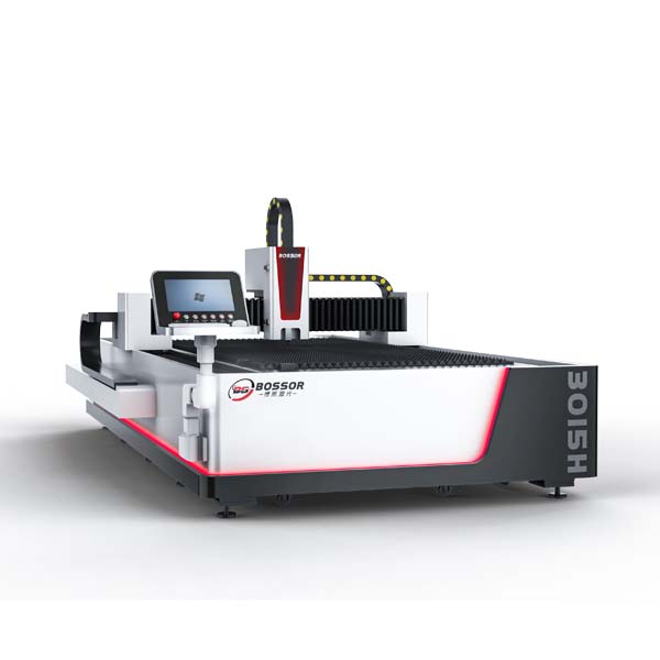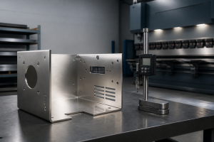
Laser cutting defects such as burrs, dross, incomplete cuts, rough edges, and burn marks can reduce cut quality, dimensional accuracy, and production efficiency.
Most defects are caused by incorrect laser power, cutting speed, focus position, assist-gas pressure, nozzle alignment, or contaminated optics. This guide explains the most common laser cutting defects, their causes, and practical solutions for carbon steel, stainless steel, and other sheet metals.
Common Laser Cutting Defects and Solutions
| Defect | Common Causes | Practical Fix |
|---|---|---|
| Burrs | Speed, focus, gas pressure, nozzle alignment | Adjust parameters and check nozzle |
| Dross / Slag | Gas pressure, speed, focus | Optimize gas and cutting parameters |
| Incomplete Cutting | Low power, high speed, low gas pressure | Increase power or reduce speed |
| Rough Cutting Edge | Dirty lens, damaged nozzle, unstable parameters | Clean optics and replace nozzle |
| Burn Marks | Excessive heat input, incorrect focus | Reduce heat input and adjust focus |
| Yellow Cutting Edge | Nitrogen contamination | Check nitrogen purity |
| Uneven Cutting | Focus, nozzle alignment, material deformation | Check alignment and parameters |
| Cutting Line Deviation | Nozzle/optical alignment, mechanical issues | Check nozzle and optical path |
How to Diagnose Laser Cutting Problems
When a laser-cut edge shows a defect, check the problem in this order:
1. Identify the defect pattern
Determine whether the issue is burrs, dross, rough edges, incomplete cutting, discoloration, or deformation.
2. Check cutting speed and laser power
Incorrect energy input is one of the most common causes of poor cutting.
3. Check focus position
An incorrect focus can produce burrs, incomplete cuts, and unstable kerf quality.
4. Check assist-gas pressure and purity
Gas problems can cause dross, burrs, discoloration, and incomplete cutting.
5. Inspect the nozzle and lens
A damaged or contaminated nozzle or lens can cause uneven or rough cuts.
6. Check material condition
Inspect the sheet for rust, surface contamination, deformation, excessive heat, or inconsistent material quality. Material condition can affect cutting stability even when machine parameters are correct.
7. Run a test cut
After adjusting one parameter, perform a test cut before changing multiple settings at once.
8. Change one parameter at a time
Change only one parameter before each test cut. Adjusting speed, power, focus, and gas pressure at the same time makes it difficult to determine which change solved the defect. Record each adjustment and compare the cutting result before making the next change.
Carbon Steel Laser Cutting Defects
1.Eccentric Perforation and Irregular Cutting Holes
.jpg)
During the laser cutting process, if there are defects such as eccentric perforation or irregular cutting circle, the possible reasons include misalignment of the lens center, blockage of the nozzle hole or non-circular hole shape, or deviation of the laser light path. Such problems usually lead to unstable cutting starting point and affect the overall cutting quality.
In order to solve the above problems, it is necessary to check whether the center position of the lens is correct, confirm whether the nozzle hole is clean and regular in shape, and also check whether the entire light path is offset and correct it by re-targeting to ensure the accuracy of the laser path.
2.Poor Perforation Edges, Cracks, and Burrs
.jpg)
Another common defect is cracks and burrs on the edge of the perforation, or even deformation of the hole. These problems may be caused by the lead-in wire being too long or the lead-in method being improper, resulting in an unstable cutting start process. In addition, if the selected wire type is inappropriate, the perforation time is too long, or there is too much heat input during the cutting process, it will also aggravate edge erosion or burrs.
For such situations, the length and method of the lead-in wire should be optimized to ensure its rationality, and the cutting wire type that matches the material and process should be selected. The perforation time should be controlled within two seconds, and the duty cycle during cutting should be appropriately reduced by 2% to 3% each time to reduce heat accumulation and improve cutting quality.
3.Burnt Cutting Edges and Excessive Dross
.jpg)
During the laser cutting process, if the cutting edge is burnt, the burrs are severe, or the slag is obvious, the possible reasons include too high cutting gas pressure, too high laser focus position, too high laser power setting, or poor quality of the material used. These factors will cause heat to accumulate at the edge of the cut, resulting in an uneven cut surface or even ablation.
To solve such problems, you can try to appropriately reduce the pressure of the cutting gas, each adjustment within 0.1 bar, and check the focus position to ensure that it is in the best focus state. If necessary, the laser power setting should also be reduced, and the performance of the material itself should be checked to confirm whether it is suitable for the current process parameters.
4.Incomplete Cutting and Intermittent Edges
.jpg)
If the cutting is not thorough, the edge is discontinuous, or the slit is interrupted, it is usually due to insufficient laser power, too fast cutting speed, or insufficient gas pressure. This problem will cause the laser to not completely penetrate the material during the cutting process, resulting in incomplete slits or interruptions.
To deal with this situation, you can increase the energy density by increasing the laser power, or appropriately reduce the cutting speed to extend the action time of the laser and the material. At the same time, increasing the pressure of the auxiliary gas can also help remove slag and improve the cutting effect, thereby obtaining a smoother cutting edge.
5.Rough Cutting Surfaces and Uneven Edges
.jpg)
When the cut part has a rough surface, uneven texture or even edge deformation, it may be due to excessive local heat accumulation during the cutting process, causing the material to deform due to heat, or there is a problem with the quality of the material itself, resulting in unstable cutting effect and rough cut surface.
To solve this problem, the heat distribution can be optimized by adjusting the cutting order to avoid heat concentration in local areas. It is also recommended to replace materials with better quality and stronger adaptability to improve the overall quality and consistency of the cutting surface.
6.Ripples and Striations on the Cutting Edge
.jpg)
If regular or irregular wavy lines appear on the edge of the cut piece, it is usually caused by too high gas pressure or too fast cutting speed. This situation will make it impossible to blow off the slag in time, shorten the laser action time, and ultimately affect the smoothness of the cut surface.
To avoid such problems, the auxiliary gas pressure can be appropriately reduced. It is recommended to adjust the range to 0.1~0.2 bar each time. At the same time, the cutting speed should also be reduced to make the laser energy more effective, thereby improving the flatness of the cut surface and reducing the generation of ripples.
7. The bottom surface has melting points and burrs
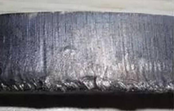
When melting points and burrs appear on the bottom of the cut piece, it is mostly because the speed is too fast, the air pressure is too low, and the focus is below the surface, which directly affects the cutting and forming effect. When adjusting, you need to reduce the speed, increase the air pressure, and move the focus to the upper part of the surface.
8.Localized overheating
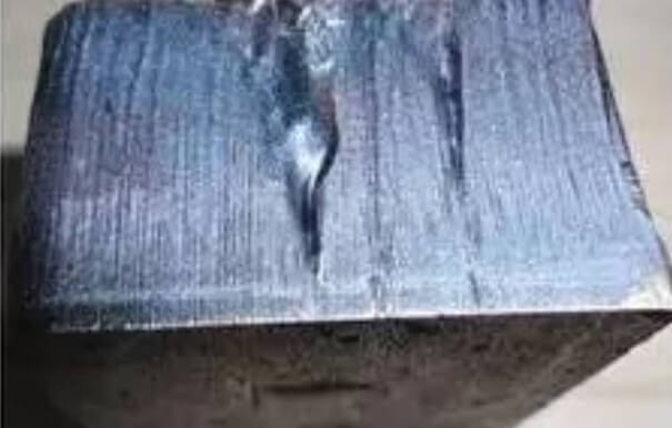
Partial overburning of the cut part is usually caused by impurities in the plate, uneven surface material, and excessive air pressure, which leads to local overburning. It is necessary to check the quality of the plate and adjust the air pressure reasonably to improve the overburning problem.
9.Interface overheating
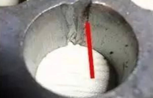
Overburning of the cutting interface is often caused by not using the arc lead-in in a standardized manner (the recommended R is 1.5 mm, and the radius of the straight line and the circle are equal). When processing, it is necessary to check the lead-in method and adjust the arc parameters according to the standard. If the back side is overburned, it is necessary to leave material for processing to ensure the quality of the interface cutting.
10.Laser Cutting Burr Patterns and Causes
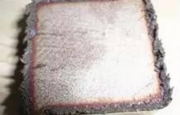
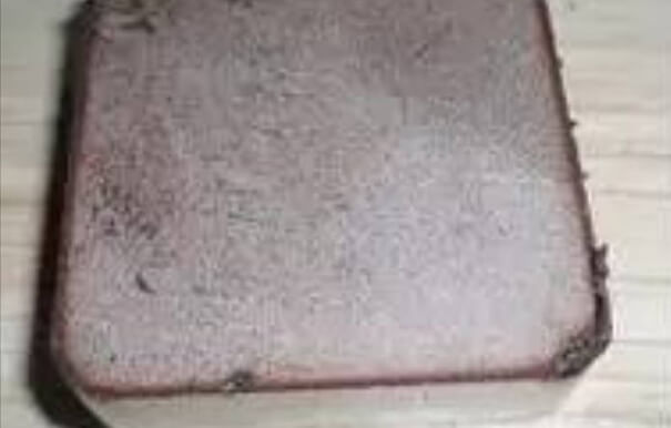
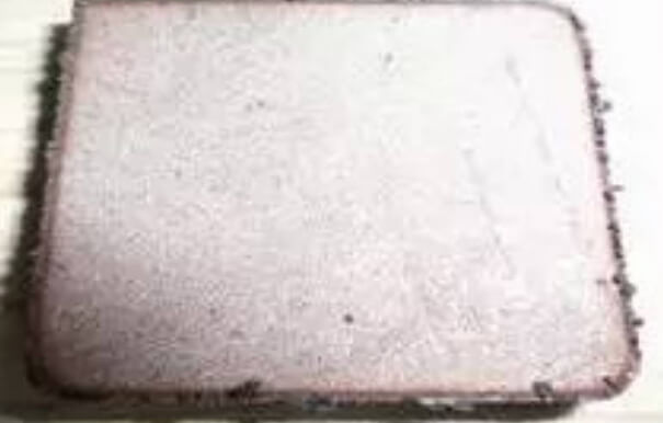
| Burr Pattern | Likely Cause | Recommended Check |
|---|---|---|
| Small regular burrs on both sides | Focus too low, cutting speed too high | Raise focus and reduce speed |
| Long irregular burrs on both sides | Low speed, high focus, low gas pressure | Increase speed and gas pressure |
| Long burrs on one side | Nozzle misalignment or uneven gas flow | Re-center the nozzle |
11.Low Oxygen Purity and Excessive Dross

When the oxygen is impure, even if the power is high, there will still be slag on the back of the cuttingaccompanied by the phenomenon that the gas pressure exceeds the normal standard and the speed cannot beincreased. This is because the oxygen purity is insufficient, which cannot effectively support combustion andremove slag, resulting in an imbalance of cutting process parameters, affecting cutting quality and efficiency.
12.Small Regular Burrs on Both Sides
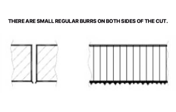
Small regular burrs on both sides of the slit are caused by the focus position being too low and the cutting speed being too high. To solve this problem, you need to increase the focus position and reduce the cutting speed to make the parameters adapt to the cutting requirements.
13. Long Irregular Burrs on Both Sides
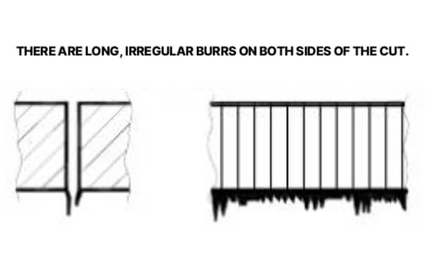
Long irregular burrs on both sides of the slit are caused by low cutting speed, high focus position, low gas pressure or overheated material. Solutions include increasing cutting speed, lowering focus position, increasing gas pressure, and cooling if the material is overheated.
14.Long Linear Burrs Caused by Nozzle Misalignment
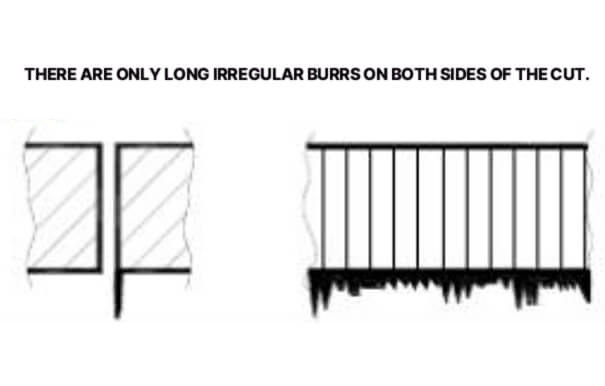
There are only long irregular burrs on both sides of the slit, which are caused by the nozzle not being in the center, the focus position being too high, the gas pressure being low or the cutting speed being low. When dealing with this problem, you need to adjust the nozzle to the center position, lower the focus height, increase the gas pressure, and increase the cutting speed.
Stainless Steel Laser Cutting Defects
Yellow or Discolored Cutting Edges
Caused by impure nitrogen (containing oxygen). To solve this problem, you need to use high-purity nitrogen to ensure gas purity and avoid discoloration of the cutting edge caused by oxidation.
Plasma Generation and Incomplete Cutting
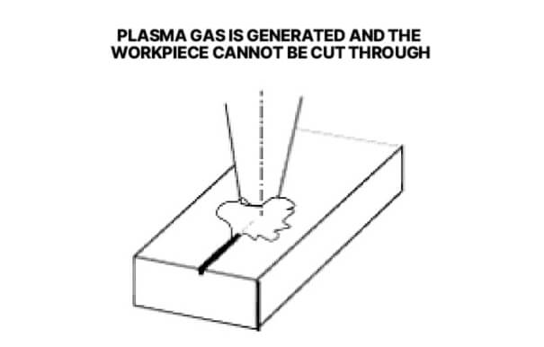
This is caused by too high cutting speed, insufficient laser power, and too low focus position. To solve this problem, you need to reduce the cutting speed, increase the laser power, and at the same time increase the focus position so that the parameters match the cutting requirements.
Beam Interruption During Cutting
Caused by too high cutting speed, low laser power and low focus position. The solution is to reduce the cutting speed, increase the laser power, increase the focus position and ensure stable beam output.
Rough Cutting Edges
Caused by nozzle damage or lens contamination. To solve the problem, you need to replace the damaged nozzle and clean the contaminated lens. If the problem still cannot be improved after cleaning the lens, replace the lens directly to ensure the quality of the cutting surface.
Low Nitrogen Purity and Yellow Cutting Edges
Impure nitrogen will make the cut surface blue or purple (normally it should be white), and will also cause slag on the back of the cut. In addition, it is not recommended to use it for a long time because it will contaminate the focusing lens. This is because the nitrogen purity is insufficient and the cutting environment cannot be maintained stably, which not only affects the cooling and slag removal effect, but also causes damage to the equipment components.
Equipment and Material Problems That Affect Laser Cutting
1. Nozzle Damage or Misalignment
.jpg)
.jpg)
Quality problems in stainless steel cutting are mainly caused by nozzle damage and insufficient observation during equipment operation. Prevention requires increased vigilance for wearing parts (such as nozzles), inspection and replacement; at the same time, strengthen observation during equipment operation, timely discover and handle abnormalities, and ensure stable cutting quality.
.jpg)
.jpg)
Quality problems in stainless steel cutting are caused by excessive cutting speed, damaged cutting parts, and non-vertical gun heads. Prevention requires controlling the cutting speed, strengthening the inspection and replacement of vulnerable parts, and increasing observation during equipment operation, implementing equipment inspections, and ensuring normal cutting.
2. Protective Lens and Optical Path Problems
.jpg)
Large burrs may persist even after cutting parameters have been checked. In such cases, abnormal consumable parts such as the protective lens or nozzle, or problems in the internal or external optical path, may be responsible. Inspect the protective lens and nozzle first, and perform optical path maintenance if the problem continues.
.jpg)
.jpg)
Some cutting problems are caused by abnormal equipment conditions rather than incorrect cutting parameters. When a defect cannot be resolved through normal parameter adjustments, review the equipment abnormalities recorded during operation and eliminate the underlying issue before continuing production.
3.Material Contamination and Plate Deformation
.jpg)
The plate undergoes stress deformation during processing, causing the secondary cutting points that should have overlapped in the program to deviate during actual cutting. To prevent this, the program needs to be modified appropriately according to the plate deformation, and the cutting seams should be overlapped as much as possible (if the deformation is large and affects the dimensional accuracy, there is currently no better solution).
.jpg)
The plate deforms due to stress during processing, resulting in deviations in the actual cutting of the overlapping secondary cutting points in the program. For prevention, when processing plates with an aspect ratio greater than 1:10, try to use the whole plate for processing, or first spot weld the narrow plate and then cut it in sections to reduce the deviation caused by deformation.
.jpg)
The board surface is polluted because there are many footprints on the board surface and the quality protection awareness is weak. Prevention requires strengthening the "three preventions" publicity, improving the quality protection awareness of the board, and placing signs to remind operators that hard-to-clean stains can be erased with an eraser.
.jpg)
Cutting size deviation, stress deformation of the plate during processing, or falling into the depression of the support plate will cause the program to cut the next specification on the finished product, resulting in actual size deviation. Prevention requires strengthening the control of the processing process, timely detection of abnormal conditions, and avoidance of losses.
4.Support Bed and Slag Accumulation
.jpg)
.jpg)
The defect of missing 5mm matrix from the outer circle often occurs at the end of the part cutting track or the starting point of another part. It is caused by insufficient support of the part, which tilts on the support bed and interferes with the cutting track. Prevention needs to start from two aspects. First, fully consider the safety of the cutting track during programming to reduce the risk of accidents; second, the operator should strengthen observation during the cutting process and clean up the tilted parts in time to avoid interference problems.
.jpg)
.jpg)
Burning of the edge of the part. This defect is caused by spare parts problems and slag accumulation on the water bed, which makes it impossible to drain the slag produced by cutting. It accumulates on the lower surface of the part and burns the edge of the product (only occurs when cutting thick plates). Prevention requires strengthening the control of vulnerable spare parts, timely detection and replacement; at the same time, clean the water bed in time. If a problem is found, immediately interrupt the processing to avoid burns.
.jpg)
Cutting slag rebound residue, due to the rebound of slag residue during cutting, causes problems. Prevention requires regular cleaning of accumulated slag on the support plate to reduce the slag accumulation area, which can effectively avoid the cutting slag rebound phenomenon.
5.Programming and Machine Setup Errors
.jpg)
Cutting anomalies are caused by programming problems. This defect is caused by deficiencies in the programming process. To prevent it, it is necessary to fully consider the utilization rate of residual materials during program design and avoid such problems by optimizing the programming solution.
.jpg)
The cutting node is abnormal. This defect is caused by programming problems. Prevention requires adjusting the lead-in and lead-out methods to reduce node protrusion, but this method has the potential risk of increasing local injuries, which needs to be weighed in actual operation.
.jpg)
Cutting defects are caused by lax trial operation before processing. The reason is that the trial operation before processing is not strictly implemented. Prevention requires strengthening skill training, standardizing operating procedures, and clarifying that effective trial operation must be carried out before cutting. Through rigorous trial operation, potential problems can be checked to avoid cutting defects caused by omissions in the preparation process.
.jpg)
The cutting path is offset because the operator neglects to observe and fails to avoid obstacles on the processing route in time, causing the gun head to hit the fixed wood, which eventually causes the cutting line to deviate. Prevention requires strengthening skill training, standardizing operating procedures, strictly implementing effective trial runs before cutting, and checking obstacles in the processing route in advance to avoid cutting abnormalities caused by operational omissions.
.jpg)
.jpg)
Cutting defects are caused by on-site operational errors. This defect is caused by errors in the operation process. To prevent it, it is necessary to strengthen the skills training of operators and strengthen the awareness of product quality protection to reduce the occurrence of such defects from the operational level.
.jpg)
The cause of abnormal perforation defects has not been fully identified. It is speculated that it may be related to the conditions and reliability of the equipment's internal program for determining whether perforation is complete. Prevention requires more observation of equipment operation, recording and retaining original data to provide support for subsequent maintenance and improvement.
.jpg)
.jpg)
The cutting surface may become abnormal because of equipment instability or problems with consumable parts. Prevention requires regular equipment inspections and checks of consumable parts to identify potential problems before they affect cutting quality.
.jpg)
The cutting surface is abnormal, because the cutting was not completely through, and the subsequent re-cutting caused problems. Prevention requires setting appropriate cutting parameters before cutting. It is recommended to use the remaining board of the same specification for trial cutting, and determine the precise parameters through trial cutting to avoid the situation of incomplete cutting and re-cutting.
.jpg)
.jpg)
The edge of the parts is damaged. When cleaning the parts, due to negligence, the parts collide with each other without paying attention, which eventually leads to edge damage. Prevention requires strengthening quality promotion, improving the operators' awareness of protecting the quality of finished products, standardizing cleaning operations, and avoiding damage caused by parts collision.
Common Fiber Laser Cutting Problems and Solutions
Fiber laser cutting problems can appear as burrs, incomplete cuts, rough edges, discoloration, unstable beams, or cutting-line deviation. These problems are usually related to cutting speed, laser power, focus position, assist gas, nozzle condition, or the optical system. The following troubleshooting guide summarizes the most common fiber laser problems and practical ways to address them.
1.Burrs and Dross
Burrs and dross are among the most common fiber laser cutting problems. They can result from excessive or insufficient cutting speed, an incorrect focus position, unsuitable assist-gas pressure, or nozzle misalignment. Check the burr pattern first, then adjust one parameter at a time. For carbon steel, also check oxygen purity because insufficient oxygen purity can increase dross. If burrs remain after parameter adjustments, inspect the nozzle and protective lens for damage or contamination.
2.Incomplete Cutting or Poor Penetration
Incomplete cutting usually means that the laser does not provide enough effective energy to fully penetrate the sheet. Common causes include insufficient laser power, excessive cutting speed, unsuitable focus position, or insufficient assist-gas pressure. Start by checking the cutting speed and laser power, then verify the focus position and gas supply. If the problem occurs only on certain sheets, inspect the material condition and thickness. Run a test cut after each adjustment instead of changing several parameters at the same time.
3.Rough Cutting Edges
Rough cutting edges may indicate unstable cutting parameters or problems with the cutting head and optical system. Cutting speed, focus position, assist-gas pressure, nozzle condition, and lens cleanliness should be checked. If the roughness appears across the entire cut, compare the current speed and power with the recommended process parameters. If it appears unevenly or suddenly becomes worse, inspect the nozzle and protective lens for damage or contamination before making major parameter changes.
4.Burn Marks and Discoloration
Burn marks and discoloration usually indicate excessive heat or unwanted oxidation during cutting. On stainless steel, yellow, blue, or purple cutting edges can be related to oxygen contamination in the nitrogen supply. Check nitrogen purity and gas delivery first. Excessive heat can also result from unsuitable speed, focus, or power settings, so verify the cutting parameters if discoloration is accompanied by burning or dross. For thick-plate cutting, also check whether accumulated slag on the support bed is contributing to localized heating.
5.Beam Divergence or Unstable Cutting
Beam divergence or unstable cutting can cause sudden changes in cut quality, incomplete penetration, or uneven cutting edges. In the existing stainless steel cases, high cutting speed, insufficient laser power, and an unsuitable focus position are associated with beam divergence and plasma generation. Check these parameters first and confirm that the laser output remains stable. If the problem occurs at the beginning of the cut or around corners, also check acceleration and the programmed cutting conditions.
6.Cutting Line DeviationCutting-line deviation means that the actual cutting path does not match the programmed position. Possible causes include plate deformation, nozzle misalignment, programming errors, obstacles along the cutting path, or problems with the optical or mechanical system. Check the material support and plate condition first, then verify the nozzle alignment and program. If the deviation occurs repeatedly across different sheets, inspect the machine and optical system rather than repeatedly changing cutting parameters.
7.Nozzle and Lens Problems
A damaged or contaminated nozzle or protective lens can cause several fiber laser cutting problems at the same time, including burrs, rough edges, unstable cutting, and uneven gas flow. Inspect the nozzle for damage, blockage, deformation, or misalignment, and check the protective lens for contamination or damage. If cleaning the lens does not restore cutting quality, replacement may be necessary. When parameter adjustments do not solve a problem that suddenly appeared, checking the nozzle and optical components can help avoid unnecessary changes to the cutting parameters.
Summary of causes and solutions for laser cutting defects
1. No burrs, consistent pulling line
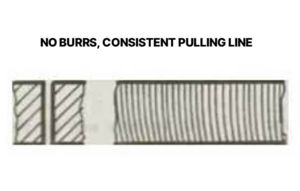
This is the ideal cutting state, because the power and feed rate are adapted. No additional processing is required, just maintain the current appropriate power and feed rate.
2. Bottom leader line offset and bottom cutout wider
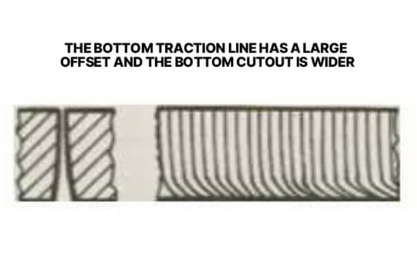
This is caused by too high feed rate, insufficient laser power, low air pressure or too high focus. To solve this problem, you need to reduce the feed rate, increase the laser power, increase the air pressure, and lower the focus height to make the parameters match the cutting requirements.
3. The burrs on the bottom surface are like slag, which are easy to remove in the form of drops.
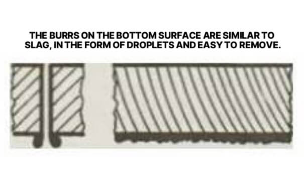
Caused by high feed rate, low air pressure or high focus. The treatment method is to reduce the feed rate, increase the air pressure, lower the focus, and optimize the cutting conditions to reduce this type of burr.
4. Connected metal burrs can be removed as one piece
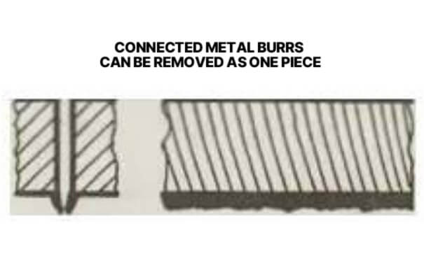
This is caused by the focus being too high. To solve this problem, you need to lower the focus position, adjust the cutting focus to a suitable height, improve the cutting quality, and eliminate this type of burr.
5. Metal burrs on the bottom surface are difficult to remove
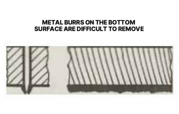
Possible causes: feed rate too high, air pressure too low, impure gas, focus too high. Solution: reduce feed rate, increase air pressure, use purer gas, lower focus.
6. Burrs only on one side
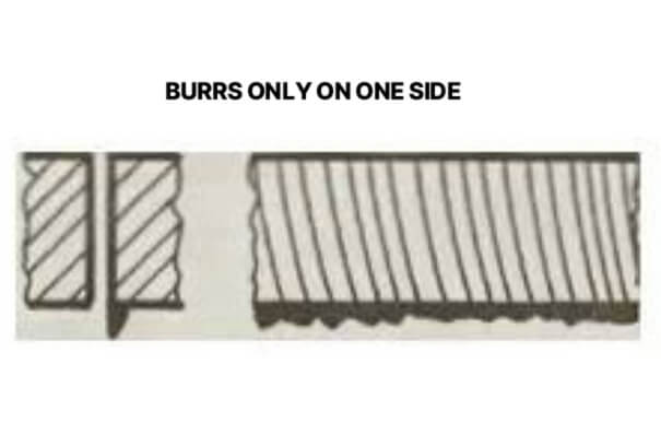
Possible causes: incorrect nozzle alignment, defective nozzle opening. Solution: Align the nozzle, replace defective nozzle.
7. Material is discharged from above
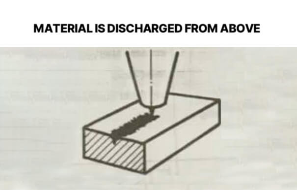
Treatment measures: Press the pause button immediately to prevent slag from splashing onto the focusing lens. Then increase the laser power and reduce the feed rate.
8.Inclined surface cutting, two sides good, two sides bad

Possible reasons: The total reflector is not suitable, is not installed correctly or is defective; the total reflector is installed in the position of the deflection mirror. Solution: Check the total reflector; check the deflection mirror.
9.Blue plasma, workpiece not cut through
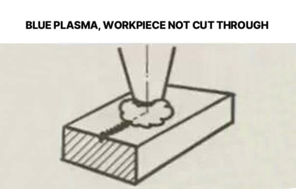
Possible causes: Wrong processing gas; Feed rate too high; Power too low. Solution: Press the Pause button immediately to prevent slag from splashing onto the focusing lens; Use oxygen as processing gas; Reduce feed rate; Increase power.
10.Imprecise cutting surface
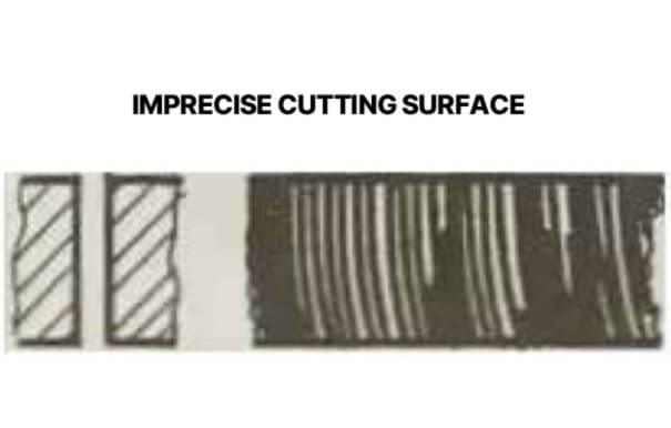
Possible reasons: air pressure is too high; nozzle is damaged; nozzle diameter is too large; material is not good.
Solution: reduce air pressure; replace nozzle; install suitable nozzle; use material with smooth and uniform surface.
11.No burrs, the pull line is inclined, and the cut becomes narrower at the bottom
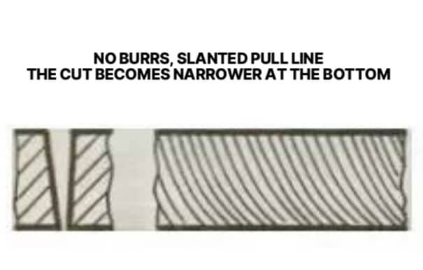
Possible cause: Feed rate is too high. Solution: Reduce feed rate.
12.Create crater
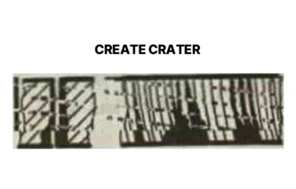
Possible reasons: air pressure is too high; feed rate is too low; focus is too high; rust on the plate surface; overheating of the workpiece being processed; impure material. Solution: reduce air pressure; increase feed rate; reduce focus; use better quality material (no rust, avoid overheating, ensure material purity).
13.Very rough cut surface
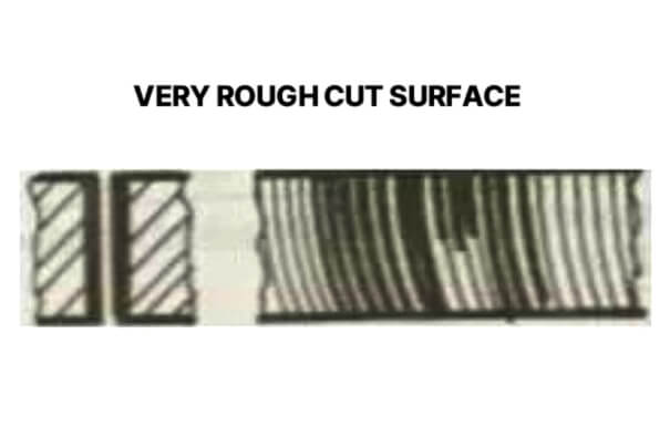
Possible causes: Focus too high; Air pressure too high; Feed rate too low; Material too hot. Solution: Lower the focus; Reduce air pressure; Increase feed rate; Cool the material.
Stainless Steel Laser Cutting Problems: N₂ Cutting
1.Small Drop-Shaped Burrs
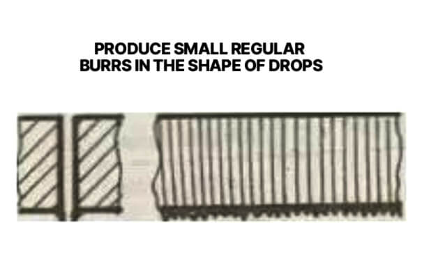
When stainless steel is cut with N₂ high pressure, various defects often occur. If tiny regular burrs in the shape of drops are produced, it is mostly because the focus is too low and the feed rate is too high. You need to raise the focus and reduce the feed rate.
2.Long Burrs and Discoloration on Large Plates
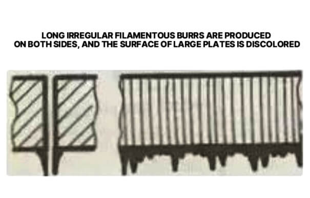
Long irregular filamentous burrs appear on both sides and the surface of large plates is discolored, which is often caused by low feed rate, high focus, low air pressure or overheating of the material. Increase the feed rate, reduce the focus, increase the air pressure and cool the material.
3.Long Burrs on One Side of the Cut
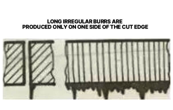
If there are long irregular burrs on only one side of the cutting edge, it may be that the nozzle is not centered, the focus is high, the air pressure is low or the speed is low. You need to center the nozzle, lower the focus, increase the air pressure and increase the speed.
4.Yellow Cutting Edges
The yellowing of the cutting edge is due to the presence of oxygen impurities in nitrogen. High-purity nitrogen needs to be used to ensure cutting quality and reduce defects.
5.Plasma Generation on Straight Cuts
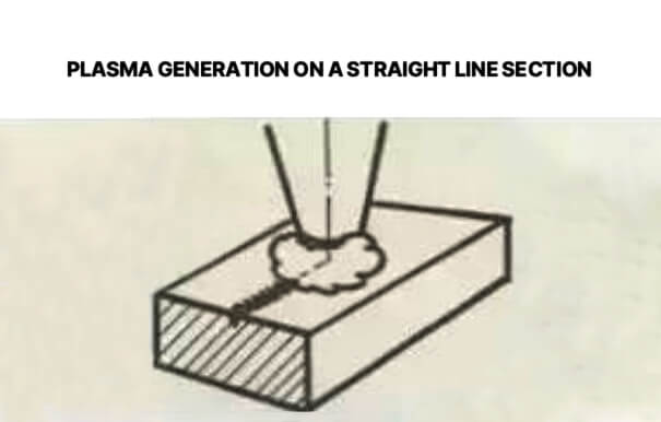
When plasma is generated on a straight section, it is because the feed rate is too high, the power is too low, and the focus is too low. At this time, press the pause button immediately to prevent the slag from splashing onto the focusing lens, then reduce the feed rate, increase the power, and raise the focus.
6.Beam Divergence During Cutting
If beam divergence occurs, the cause is also high feed rate, low power, and low focus. The solution is to reduce the feed rate, increase the power, and raise the focus.
7.Plasma Generation at Corners
Plasma is generated at the corners due to large angle tolerance, too high modulation, and too high acceleration. The angle tolerance, modulation or acceleration needs to be reduced.
8.Beam Divergence at the Start of Cutting
The light beam diverges at the beginning, which may be due to high acceleration, low focus or failure to discharge the molten material. The corresponding measures are to reduce the acceleration, raise the focus, and ensure that the molten material is discharged smoothly, so as to ensure the stability of the cutting process and improve the cutting quality.
9.Rough Cutting Edge
When the cut is rough, if the nozzle is damaged, the nozzle needs to be replaced; if the lens is dirty, the lens needs to be cleaned and replaced if necessary.
10.Material Ejection From the Top
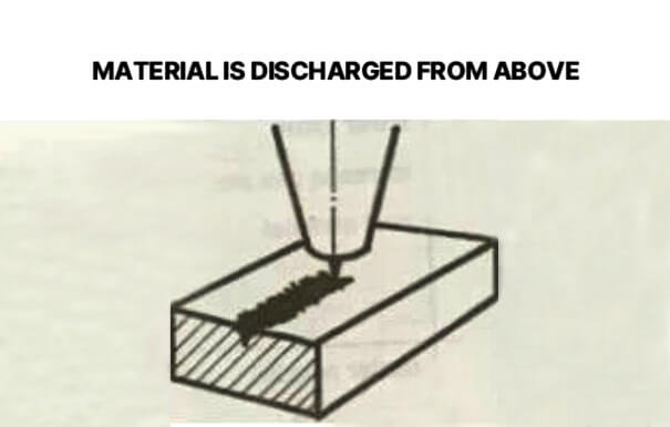
The material is discharged from the top, mainly because the power is too low, the feed rate is too high, and the air pressure is too high. In this case, press the pause button immediately to prevent the slag from splashing onto the focusing lens. Then increase the power, reduce the feed rate, and adjust the air pressure to ensure normal cutting.
Common laser cutting defects include burrs, slag, incomplete cutting, rough cutting surfaces, burn marks, uneven edges, deformation, and discoloration. These problems are usually caused by incorrect cutting parameters, such as improper laser power, cutting speed, focus position, gas pressure, or poor-quality consumables like nozzles and lenses. Proper parameter adjustment and regular equipment maintenance can effectively reduce these defects.
A laser cutter may not cut properly due to incorrect cutting parameters, insufficient laser power, excessive cutting speed, improper focus position, low gas pressure, or contaminated lenses and damaged nozzles. Material quality and thickness can also affect cutting performance. Checking and adjusting the power, speed, focus, gas pressure, and machine components can help restore normal cutting results.
The most common laser cutting problems include excessive burrs, slag formation, incomplete cuts, rough edges, burn marks, cutting surface ripples, and material deformation. These issues are often related to improper parameter settings, unstable gas supply, worn consumables, or unsuitable cutting conditions. Identifying the specific defect type helps determine the correct adjustment method.
Materials containing chlorine, such as PVC and vinyl, should never be cut with a laser because they can release toxic and corrosive gases during the cutting process. Unknown plastics and materials with unclear compositions should also be avoided. Before laser cutting, always confirm that the material is suitable and safe for laser processing.
Most metals can be laser cut with suitable equipment and parameters, but highly reflective metals such as copper, brass, and aluminum may require special laser sources, higher power, or optimized cutting settings. Thick reflective materials can be challenging because they reflect laser energy and may affect cutting efficiency and quality.
To prevent burrs in laser cutting, optimize the cutting speed, laser power, focus position, and gas pressure according to the material type and thickness. Using clean and properly aligned nozzles, maintaining lens quality, and ensuring high-purity cutting gas can also improve edge quality and reduce burr formation.
О нас
Durmapress специализируется на проектировании, производстве и продаже различного металлообрабатывающего оборудования, включая гибочные станки, ножницы, пуансоны, станки для лазерной резки и т. д. Компания была основана в 2000 году. Благодаря многолетнему опыту и накоплению технологий. DurmaPress стал одним из известных брендов металлообрабатывающего машиностроения Китая.


Свяжитесь с нами
Последние сообщения


Категории
Следуйте за нами
Еженедельное новое видео
Свяжитесь с нами для получения дополнительной информации
Если у вас есть какая-либо информация о нашей продукции, пожалуйста, свяжитесь с нами, и мы ответим вам в течение 24 часов.