О нас
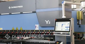
Durmapress specializes in designing, manufacturing, and selling various metal processing equipment, including bending machines, shears, punches, and laser cutting machines. The company was founded in 2014, with years of experience and technology accumulation. DurmaPress has become one of the well-known brands in China's metal processing machinery industry.


Свяжитесь с нами
Последние сообщения
Категории
Следуйте за нами
Еженедельное новое видео
Оглавление
A press brake back gauge is the positioning system that tells a sheet metal blank exactly where to stop before the ram descends, and it is the single component most responsible for bend-to-bend repeatability on a Листогибочный пресс с ЧПУ. Whether you operate a two-axis manual stop or a six-axis servo-driven system, understanding how the back gauge works — and how to keep it calibrated — directly determines your scrap rate, cycle time, and part tolerance. This guide walks through every axis configuration, component, calibration procedure, and troubleshooting scenario a fabricator needs to run a back gauge with confidence.
1. What Is a Press Brake Back Gauge?
1.1 Definition
A press brake back gauge (also written as "backgauge") is a mechanical or servo-driven positioning device mounted at the rear of a press brake. Its job is to establish a fixed reference point against which an operator (or a robotic loader) pushes a sheet of metal, so that the bend line lands in exactly the right place relative to the sheet edge.
1.2 Where It Is Located
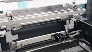
The back gauge sits behind the brake's die area, running parallel to the lower die (the V-die). It consists of a beam that travels forward and backward (toward and away from the operator), with one or more "fingers" mounted on that beam that make physical contact with the sheet.
1.3 What It Does
In practice, the back gauge automates what used to be a manual, tape-measure-and-mark process. The operator (or the machine's CNC controller, on automated systems) sets a target dimension; the gauge beam moves to that position; the sheet is slid back until it touches the fingers; the ram fires. Every bend after the first uses the same reference, which is what makes repeat parts consistent.
1.4 Why It Matters
Without an accurate back gauge, bend-line placement depends entirely on operator skill and manual measurement — a slow, error-prone approach that does not scale in production environments. A properly calibrated back gauge is what allows a shop to hold tolerances of ±0.1 mm or better across a batch of hundreds of parts, and it is often the deciding factor when evaluating an entry-level CNC press brake against a full servo-electric model.
2. How Does a Press Brake Back Gauge Work?
The back gauge operates as a closed-loop positioning cycle that repeats for every bend in a part program. Understanding this cycle clarifies why axis count and servo quality matter so much for cycle time and accuracy.
Positioning Process
- CNC positions gauge — The controller reads the target dimension from the bend program and drives the gauge beam (via ball screw and servo motor) to the exact X-axis distance from the die centerline.
- Sheet contacts fingers — The operator (or a robotic arm) slides the sheet metal blank backward until its edge makes contact with the stop fingers mounted on the gauge beam.
- Ram bends — Once contact is confirmed (either visually by the operator or via a sensor on automated cells), the ram descends and forms the bend at the pre-set angle and depth.
- Gauge retracts — After the bend, the back gauge either holds position (for a repeat bend at the same dimension) or retracts/repositions for the next step — especially important on box and pan parts where the gauge must move out of the way to avoid collision with an already-bent flange.
- Next bend — The cycle repeats, with the controller automatically indexing to the next programmed dimension until the part is complete.
Flowchart: Position → Contact → Bend → Retract → Reposition → Repeat.
This is also where the Ось R (vertical finger height) becomes critical: on multi-bend parts, the gauge fingers frequently need to drop out of the way between bends so the formed flange does not collide with them — a detail covered further in the axis breakdown below.
3. Main Components of a CNC Back Gauge
A CNC back gauge is a precision assembly of mechanical and electronic parts working together. Understanding each component helps operators diagnose faults faster and make informed purchasing decisions.
- Back Gauge Beam — The rigid structural bar that spans the width of the machine and carries the stop fingers. Beam rigidity directly affects positioning accuracy, especially on wide-bed machines where deflection can introduce error.
- Stop Fingers — The contact points that physically touch the sheet edge. Fingers are typically adjustable in height and lateral position, and many CNC systems allow independent finger control for tapered or asymmetric parts.
- Ball Screws — Convert the rotary motion of the servo motor into precise linear travel of the gauge beam. Ball screw quality (grade, preload, and lubrication) is one of the largest contributors to long-term positioning accuracy.
- Линейные направляющие — Rails and bearing blocks that keep the beam moving in a true, wobble-free straight line. Worn or contaminated linear guides are a common source of repeatability drift.
- Servo Motors — Drive the ball screws with closed-loop feedback, allowing the controller to command exact positions and velocities rather than relying on open-loop timing.
- Энкодер — Mounted on the servo motor (or sometimes directly on the ball screw/linear scale), the encoder reports actual position back to the controller in real time, enabling the closed-loop correction that makes CNC positioning accurate.
- Контроллер — The CNC or NC unit that stores bend programs, calculates required gauge positions, and commands the servo motors. Controller software also manages collision avoidance logic between the R-axis and the sheet during multi-bend sequences.
4. Types of Press Brake Back Gauges
Back gauges range from simple manual stops to fully automated multi-axis servo systems. Choosing the right type depends on production volume, part complexity, and budget.
4.1 Manual Back Gauge
- Преимущества: Low cost, simple mechanics, minimal maintenance, no electronics to fail.
- Недостатки: Slow to reposition, dependent on operator accuracy, not suitable for programmed multi-bend sequences.
- Applications: Low-volume shops, one-off prototyping, simple single-bend parts, hobbyist or educational machines.
4.2 NC Back Gauge
- Преимущества: Faster than manual, position is digitally displayed and more repeatable.
- Недостатки: Still requires manual input between steps on many models; limited automation compared to full CNC.
- Applications: Small-to-mid volume shops running moderately repetitive parts.
4.3 CNC Back Gauge
- Преимущества: High repeatability, fast changeover between part programs, supports complex multi-bend and multi-axis sequences, integrates with offline programming software.
- Недостатки: Higher upfront cost, requires trained operators/programmers.
- Applications: Production fabrication shops, contract manufacturers, shops running frequent job changes.
4.4 Servo Back Gauge
Many manufacturers market a distinct "servo back gauge" tier — a CNC back gauge where every axis (X, R, and any additional Z/X1-X2/R1-R2 axes) is driven by an independent AC servo motor with full closed-loop feedback, rather than a mix of servo and pneumatic/manual axes.
- Преимущества: The highest achievable positioning accuracy and repeatability; independent axis control enables tapered and asymmetric parts without manual intervention.
- Недостатки: Premium pricing; more axes to maintain and calibrate.
- Applications: Precision fabrication, aerospace and automotive components, shops needing tight tolerance control across varied part geometries. For shops evaluating this tier, it is worth reviewing detailed specifications on servo-driven CNC press brake models before committing to an axis configuration.
5. Press Brake Back Gauge Axes Explained
Axis configuration is the single most important spec when comparing back gauges, since it determines what part geometries the machine can handle without manual intervention.
5.1 X Axis
Function: The X-axis controls the front-to-back travel of the entire gauge beam, setting the distance from the die centerline to the stop fingers. This is the primary dimension that determines flange length. Применение: Every back gauge, from manual to six-axis, has an X-axis — it is the foundation of all bend-length positioning.
5.2 R Axis
Why It's Needed: The R-axis raises and lowers the stop fingers vertically. On multi-bend parts, a previously formed flange can physically collide with the fingers if they stay at a fixed height. Avoiding Collision: By dropping the fingers (or the entire gauge beam height) between bends, the R-axis lets the sheet clear the gauge as it is repositioned for the next bend — essential for box, pan, and enclosure parts with multiple flanges on the same edge.
5.3 Z1/Z2 Axes
Left/Right Movement: Z1 and Z2 allow the two gauge fingers to move independently left and right along the beam. This lets operators support sheets of different widths or asymmetric parts without manually repositioning fingers by hand — the controller drives each finger to its programmed lateral position automatically.
5.4 X1/X2 Axes
Tapered Parts: X1 and X2 give each finger (left and right) independent front-to-back (X) travel. This is what makes tapered or trapezoidal parts possible — the left finger can sit at a different depth than the right finger, matching a non-parallel sheet edge in a single motion.
5.5 R1/R2 Axes
Independent Height: R1 and R2 give each finger independent vertical control. This supports parts where one side of the sheet needs a different finger height than the other — for example, stepped or offset flange geometries.
5.6 2-Axis vs 4-Axis vs 6-Axis Comparison
| Конфигурация | Axes Included | Best For | Relative Cost |
|---|---|---|---|
| 2-Axis | X, R | Simple straight-flange parts, low-to-mid volume | Lowest |
| 4-Axis | X, R, Z1, Z2 | General fabrication with mixed sheet widths | Moderate |
| 6-Axis | X1, X2, R1, R2, Z1, Z2 | Tapered parts, asymmetric geometry, aerospace/precision work | Highest |
6. How to Choose the Right Back Gauge
Selecting a back gauge is a purchasing decision that should follow the shop's actual production profile rather than the highest spec sheet available. Work through these factors in order:
- Production Volume — Low-volume, high-mix shops may not recoup the cost of a 6-axis servo gauge; high-volume repeat production justifies the investment through reduced cycle time and setup.
- Part Complexity — Simple straight-flange parts need only X and R. Tapered, asymmetric, or multi-flange box parts require X1/X2, Z1/Z2, or R1/R2 to avoid manual finger repositioning.
- Accuracy Requirements — Tight-tolerance industries (aerospace, medical, precision electronics enclosures) demand higher servo resolution and repeatability than general fabrication.
- Future Expansion — Consider whether the controller and machine frame support adding axes later, or whether the part mix is likely to diversify.
- Controller Compatibility — Confirm the back gauge integrates with your existing CNC controller and any offline bend-simulation software already in use on the shop floor. This is a common gap when retrofitting an older machine — see our CNC controller compatibility guide for retrofit considerations.
- Бюджет — Balance the axis count against total cost of ownership, including maintenance and calibration complexity — more axes mean more servo motors, encoders, and wear points to service.
Recommended Axis Selection
| Production Type | Recommended Axis Configuration |
|---|---|
| Simple Parts | X + R |
| General Fabrication | X + R + Z |
| Aerospace / Precision | 6-Axis (X1/X2, R1/R2, Z1/Z2) |
7. Back Gauge Accuracy and Positioning Tolerance
Positioning accuracy is where back gauge specifications translate directly into part quality. Several distinct — and often confused — metrics describe this performance.
- Typical Positioning Accuracy: Most industrial CNC back gauges achieve ±0.02 mm to ±0.05 mm positioning accuracy per axis under standard conditions, though this varies by ball screw grade and beam length.
- Repeatability: Repeatability measures how consistently the gauge returns to the same commanded position across many cycles — typically tighter than absolute accuracy, often ±0.01 mm to ±0.03 mm on well-maintained servo systems.
- Servo Accuracy: Determined by encoder resolution (pulses per revolution) combined with ball screw lead — higher-resolution encoders allow finer position increments and tighter closed-loop correction.
- Backlash: Mechanical play in the ball screw nut or gear coupling that causes a small position error when the gauge changes direction of travel. Backlash compensation is typically programmed into the controller but degrades as components wear.
- Thermal Expansion: Extended production runs generate heat in servo motors and ball screws, causing minute dimensional changes in the beam and screw length — a factor that matters most on precision work with tolerances under ±0.05 mm.
Factors Affecting Precision: Beam rigidity, ball screw preload, linear guide condition, ambient temperature stability, finger contact surface wear, and controller backlash compensation settings all compound to determine real-world positioning tolerance — which is why routine calibration (below) is non-negotiable for tolerance-critical work.
8. Press Brake Back Gauge Calibration
Calibration restores the back gauge to its designed accuracy after wear, collision, or extended use has introduced positioning drift. Skipping calibration is one of the most common — and most avoidable — causes of scrap in bending operations.
When to Calibrate Calibrate after any detected dimensional drift, following a finger collision or crash, after replacing a ball screw or servo motor, or on a fixed preventive schedule (see frequency guidance below).
Tools Needed A certified precision measuring instrument (dial indicator or digital caliper with traceable calibration), a straightedge, a test sheet of known thickness and material, and the machine's calibration/service menu access.
Безопасность Lock out the machine's ram before performing any manual measurement near the die area. Never reach into the bending zone while the machine is powered and in cycle-ready mode. Follow your facility's lockout/tagout procedure for any adjustment requiring hand access near the gauge beam or fingers.
Step 1: Clean — Remove all dust, metal shavings, and oil residue from the gauge beam, linear guides, and finger contact surfaces. Debris on the guide rails is a frequent, easily overlooked cause of inconsistent readings.
Step 2: Measure — Using the dial indicator or caliper, measure the actual gauge position at several points across its travel range and compare against the CNC controller's displayed position to quantify any offset.
Step 3: Parallelism — Check that the gauge beam runs parallel to the die centerline across its full width using a straightedge or dial indicator sweep — a beam out of parallel introduces a taper error even if X-axis positioning reads correctly.
Step 4: Finger Adjustment — Adjust or replace worn stop fingers so their contact faces are square and at a consistent height, then re-tighten mounting bolts to the manufacturer's specified torque.
Step 5: Test Bend — Run a test bend on scrap material of the same gauge and material as production, measure the resulting flange dimension, and compare against the programmed target — adjust the controller's offset value until the measured result matches the commanded dimension within tolerance.
Calibration Frequency As a general guideline: verify daily with a quick reference-part check, perform a full measured calibration monthly, and schedule a comprehensive calibration (including parallelism and backlash checks) every six months or after any collision event — heavier-use shops should tighten this interval.
9. Common Back Gauge Problems & Troubleshooting
| Problem | Likely Cause | Решение |
|---|---|---|
| Back Gauge Not Moving | Servo drive fault, loose coupling, or E-stop engaged | Check E-stop status, inspect servo drive alarms, and verify the motor coupling is secure. |
| Wrong Position | Incorrect controller offset or uncalibrated axis | Re-verify the controller offset against the measured position and recalibrate the axis. |
| Finger Collision | R-axis not programmed to retract between bends | Update the bend program to include an R-axis retraction step and check collision avoidance settings. |
| Servo Alarm | Overload, overheating, or encoder feedback fault | Check the servo drive alarm code, inspect motor load and cooling, and verify the encoder cable connection. |
| Encoder Fault | Damaged encoder, loose cable, or contamination | Inspect and reseat the encoder cable, clean the encoder housing, and replace the encoder if the signal remains unstable. |
| Ball Screw Wear | Insufficient lubrication or extended service life | Inspect for play or looseness, relubricate according to the maintenance schedule, and replace the ball screw if backlash is excessive. |
| Backlash | Worn ball screw nut or loose coupling | Apply controller backlash compensation and replace the worn ball screw nut or coupling if necessary. |
| Repeatability Error | Contaminated linear guides, worn fingers, or thermal drift | Clean and relubricate the linear guides, replace worn fingers, and allow a machine warm-up cycle before precision production. |
| Noise | Dry ball screw, worn bearing, or loose mounting hardware | Lubricate the ball screw, inspect the bearings, and tighten all beam and motor mounting bolts. |
| Slow Movement | Servo drive parameter fault, mechanical binding, or overload | Check servo drive speed and torque parameters, inspect the guides for binding, and reduce the load if overloaded. |
10. Back Gauge Maintenance Checklist
Consistent maintenance is the most cost-effective way to preserve back gauge accuracy and avoid unplanned downtime. Structure inspection tasks by frequency:
- Daily: Wipe down the beam and fingers; visually inspect for debris or damage; confirm gauge moves smoothly across its full travel with no unusual noise.
- Weekly: Check ball screw and linear guide lubrication levels; inspect stop fingers for wear or looseness; verify a known reference dimension against the controller display.
- Monthly: Perform a full measured calibration check (Steps 2–5 above); inspect servo motor mounting and cable connections; check for backlash using a dial indicator.
- Every 6 Months: Full parallelism verification; ball screw preload inspection; encoder signal diagnostics via the controller; replace worn linear guide wipers or seals as needed.
| Частота | Maintenance Task |
|---|---|
| Daily | Wipe the back gauge beam and fingers, perform a visual inspection, and check for smooth full-travel movement. |
| Weekly | Check lubrication levels, inspect finger wear or looseness, and verify the reference dimension. |
| Monthly | Perform a full measured calibration check, inspect servo mounting and cables, and check for backlash. |
| Every 6 Months | Verify full parallelism, check ball screw preload, perform encoder diagnostics, and replace worn seals or wipers if necessary. |
11. Common Applications
- Automotive — Brackets, panels, and structural components requiring tight repeatability across high-volume runs.
- Cabinet Manufacturing — Enclosures and cabinet frames where square, consistent flange dimensions affect final assembly fit.
- HVAC Duct Fabrication — Sheet metal ductwork with long, straight flanges benefiting from stable X-axis positioning across wide beam lengths, closely related to duct sizing calculations covered in our duct sizing calculator.
- Electrical Enclosures — Precision boxes and panels where multiple flanges on the same part demand reliable R-axis collision avoidance.
- Elevator Manufacturing — Cabin panels and structural components requiring consistent large-format bending accuracy.
- Steel Furniture — Frames and structural pieces where visible seams make dimensional consistency a cosmetic as well as functional requirement.
- Kitchen Equipment — Stainless steel fabrication for commercial kitchens, where hygiene-grade finishes demand accurate first-pass bends to avoid rework marks.
- Heavy Machinery — Thick-gauge structural components where beam rigidity and servo torque under load are critical to holding tolerance.
12. FAQ
A press brake back gauge is a positioning device mounted behind the die area of a press brake that stops sheet metal at a precise, repeatable distance from the bend line, ensuring consistent flange dimensions across a production run.
The X-axis controls the front-to-back distance of the entire gauge beam from the die centerline, setting the primary flange length dimension for each bend.
A daily quick reference check, a full monthly calibration, and a comprehensive six-month calibration (including parallelism and backlash) is a reasonable baseline for most production shops; increase frequency after any collision or for tolerance-critical work.
In some cases, yes — retrofitting a manual gauge with a servo motor, ball screw, and CNC controller integration is possible, but feasibility depends on the machine's existing frame and controller compatibility, so a manufacturer or qualified integrator should assess the machine first.
Common causes include ball screw backlash, worn linear guides, encoder faults, thermal expansion during long runs, loose or worn stop fingers, and debris on the beam or guide rails.
The X-axis controls front-to-back beam travel (setting flange length), while the R-axis controls the vertical height of the stop fingers, allowing them to drop clear of previously formed flanges during multi-bend sequences.
Most industrial CNC back gauges achieve positioning accuracy in the ±0.02 mm to ±0.05 mm range, with repeatability often tighter, though actual performance depends on beam length, ball screw grade, and maintenance condition.
Box and pan parts with multiple flanges typically require at minimum an R-axis for collision avoidance, and often benefit from Z1/Z2 independent finger positioning to handle varying flange widths without manual adjustment.
Simple straight-flange parts need only X and R; general fabrication with mixed part geometries benefits from X, R, and Z axes; tapered, asymmetric, or aerospace-grade parts typically require a full 6-axis configuration (X1/X2, R1/R2, Z1/Z2).
An NC back gauge offers motorized, digitally displayed positioning but limited program automation between steps, while a CNC back gauge is fully integrated with the machine's controller to store and execute complete multi-bend programs automatically.
Stay Updated on Industrial Innovations
Subscribe to our newsletter for the latest insights on manufacturing technology, sustainability, and industry trends.