1 Overview.....................................................................................................................................3
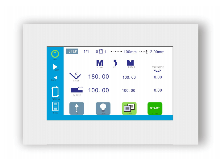
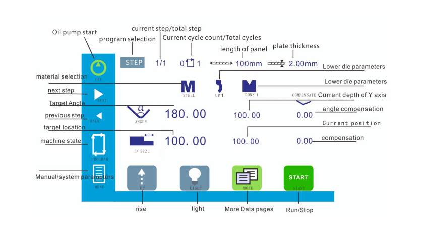
1.1 Programming/running............................................................................................................3
1.2 More programming................................................................................................................3
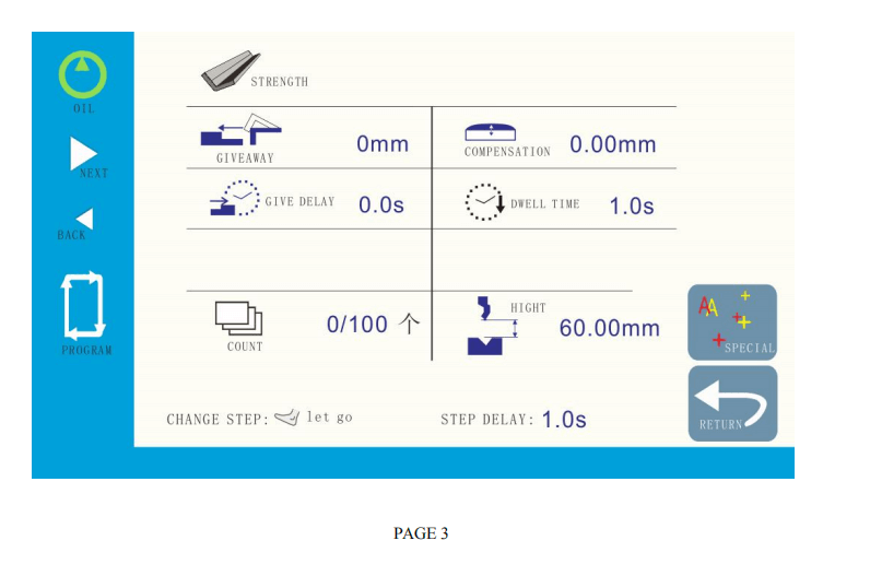
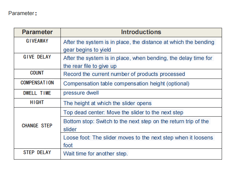
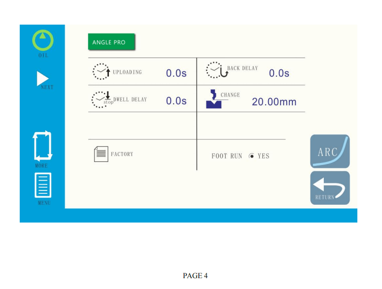
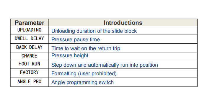
1.3 Advanced parameters............................................................................................................. 4
1.4 Mode selection.......................................................................................................................5
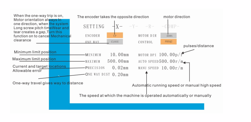
1.5 System parameter...................................................................................................................6
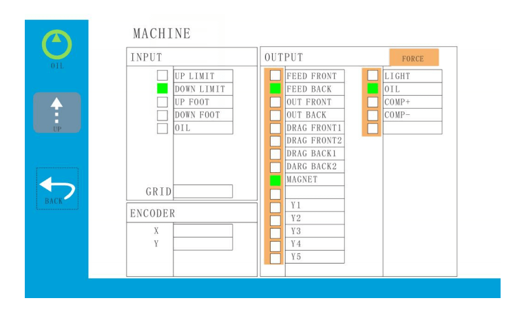
1.6 Machine diagnosis................................................................................................................. 6
2.Debugging system................................................................................................................7
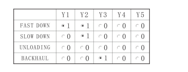
2.1 Valve settings.......................................................................................................................... 7
2.2 Coefficient.............................................................................................................................. 8
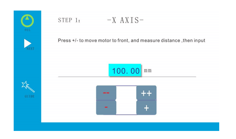
2.2.1 X axis....................................................................................................................................8
2.2.2 Y axis................................................................................................................................... 8
2.3 Angle Debugging.................................................................................................................... 9
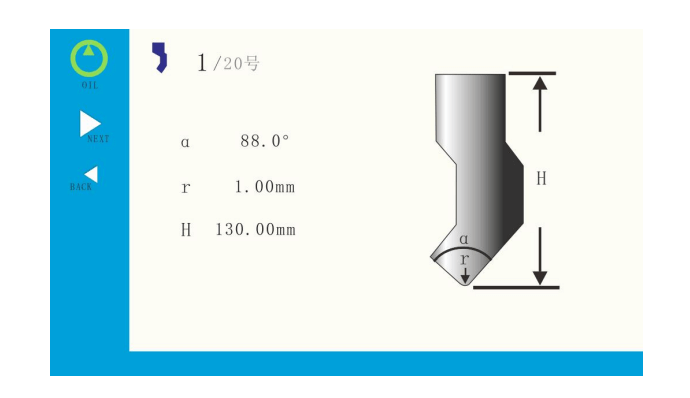
2.3.1 Upper mold..........................................................................................................................9
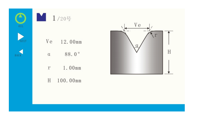
2.3.2 Lower mold..........................................................................................................................9
2.3.3 Other parameter.................................................................................................................10
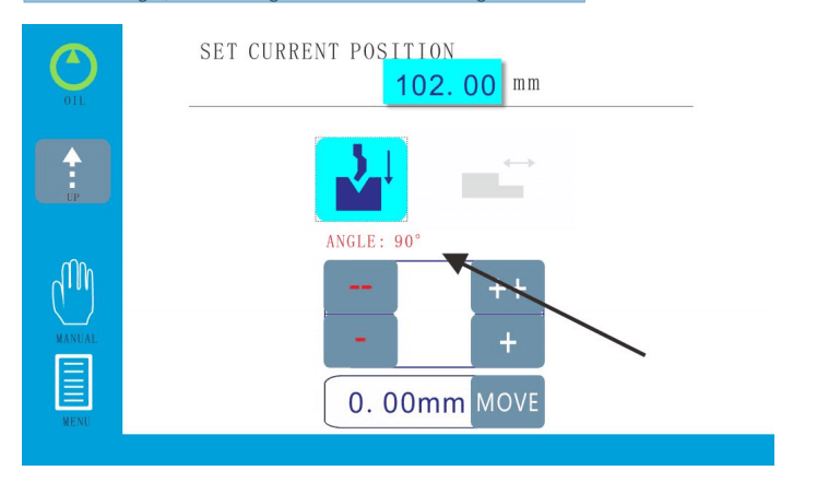
2.4 Angle calibration.................................................................................................................. 10
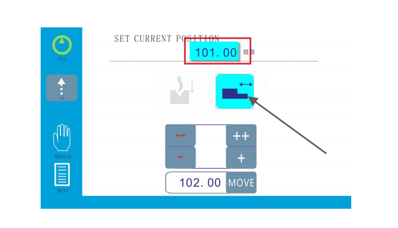
2.5 Length of calibration.............................................................................................................11
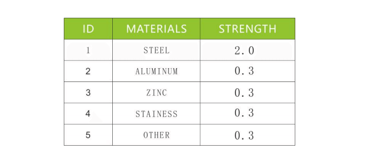
2.6 Frame strength......................................................................................................................12
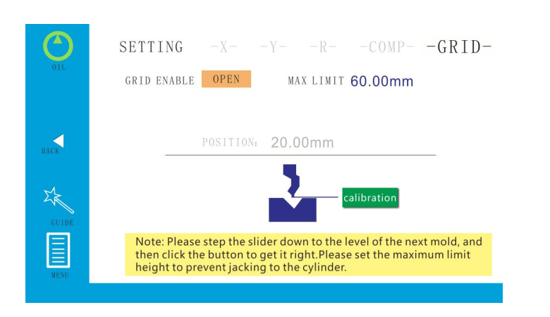
2.7 Grid ruler.............................................................................................................................. 12
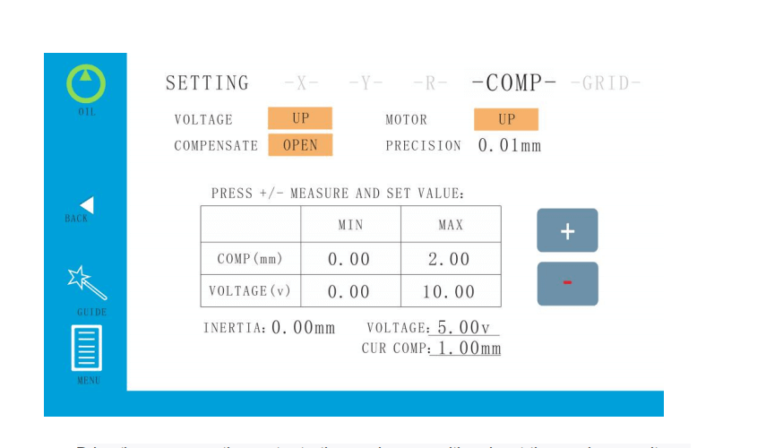
2.8 Mechanical compensation................................................................................................... 13
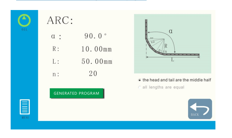
2.9 Great arc............................................................................................................................... 13
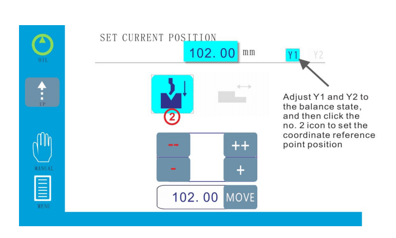
2.10 Y1-Y2 axis.............................................................................................................................14
3.User operation.....................................................................................................................14
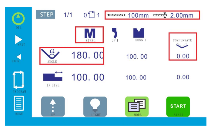
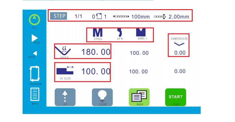
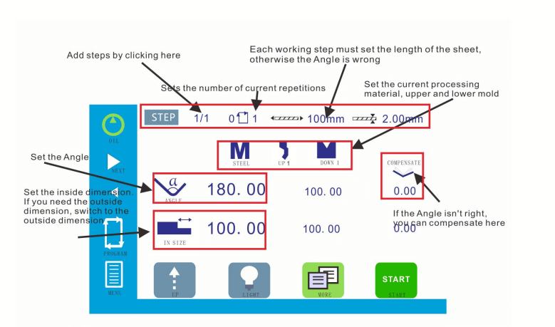
3.1 Single step programming..................................................................................................... 14
3.2 Multi-step programming......................................................................................................15
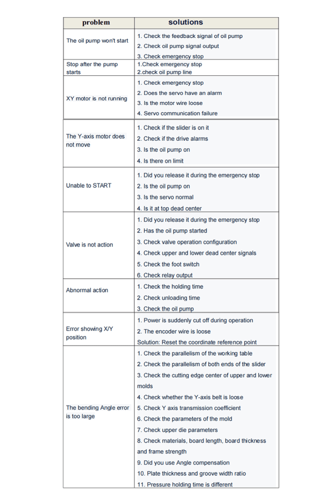
4.Common problem...............................................................................................................15