1.overview
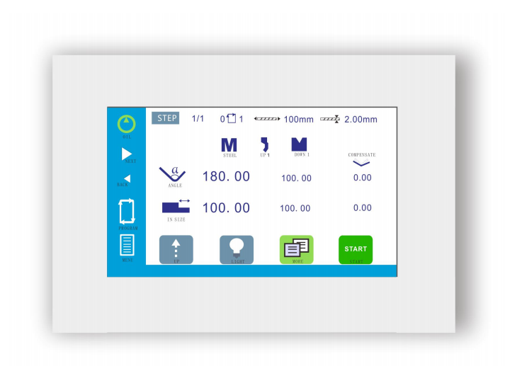
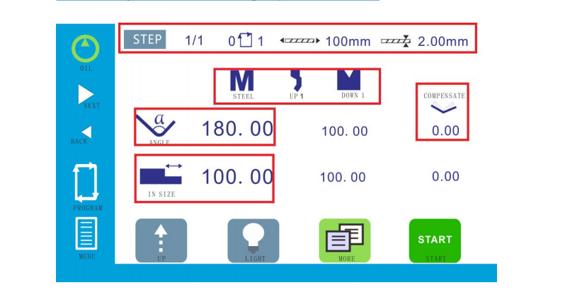
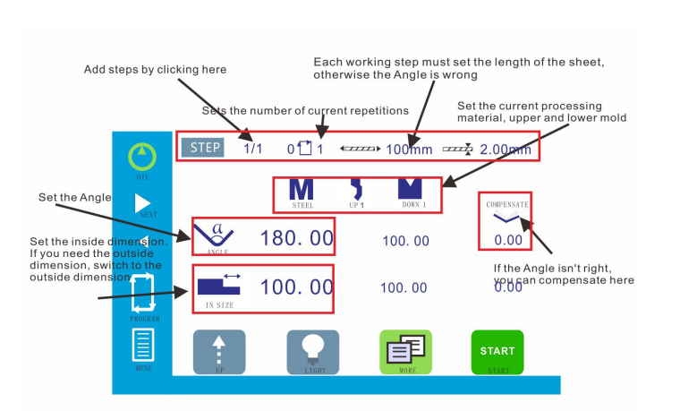
1.1 programming/running

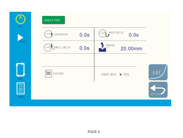
1.2 More Programmin
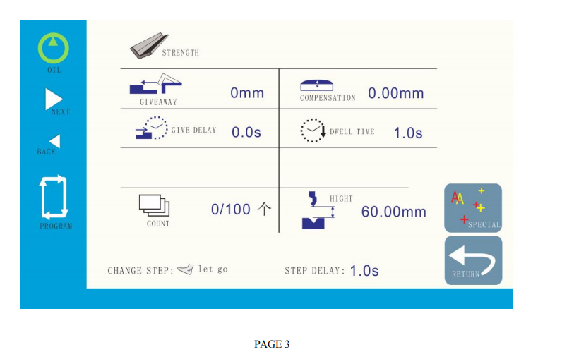
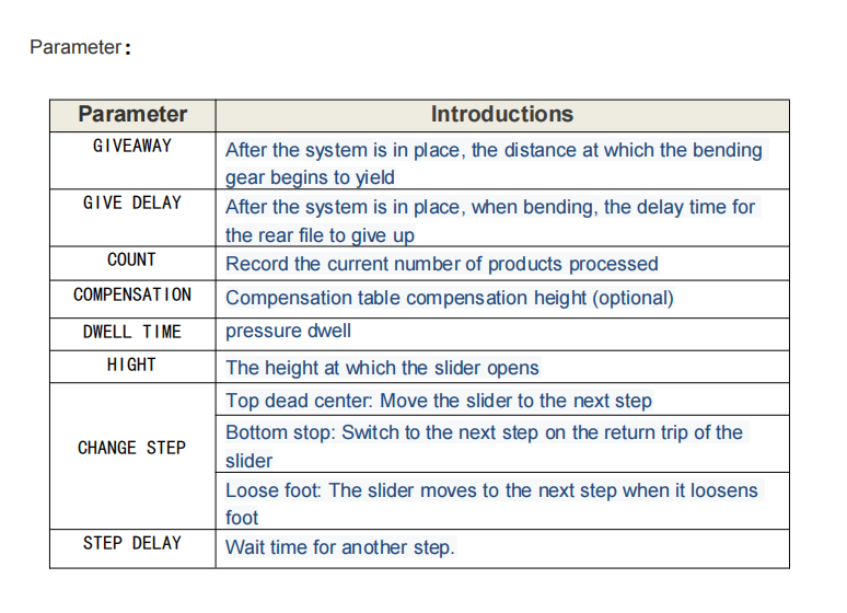
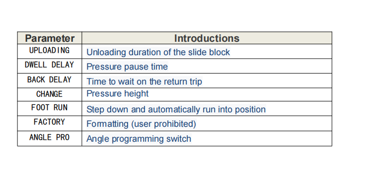
1.3 advanced parameters

1.4 mode selection

Inching: Inching controlSingle: Automatic return after the end of a single bendContinuous: Automatic cycle operation
1.5 machine diagnosis
Machine state allows you to view all the state of the machine: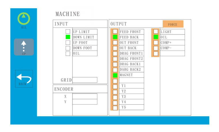
2.debugging system
When the system is used for the first time, it is necessary to debug the machine to achieve the purpose of users.
You need to do the following steps for debugging.
2.1 valve settings
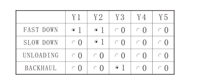
Go down: Go down.
Slow down: Pressure action.
Unloading: Unloading action.
Backhaul: Backhaul action.
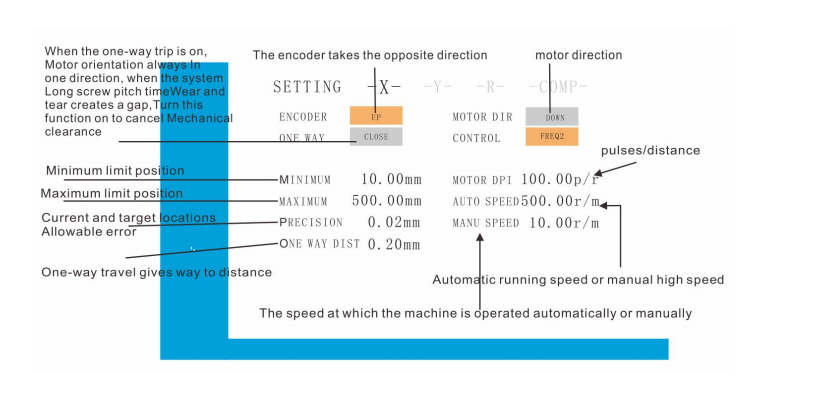
2.2 coefficient
2.2.1 X axis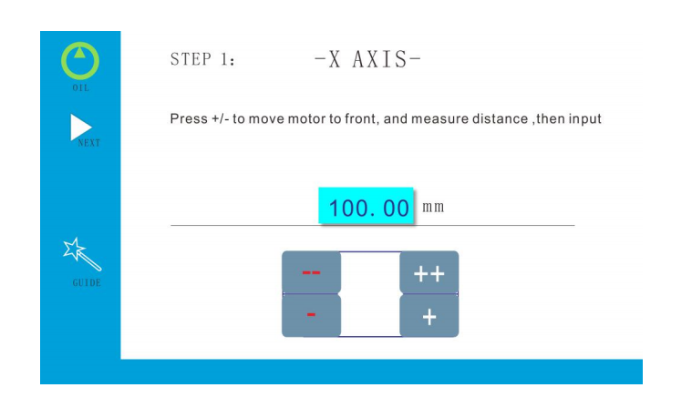
Following the steps above, you are ready to adjust the bending Angle.
2.3 angle debugging
First, we set the upper and lower mold sizes:
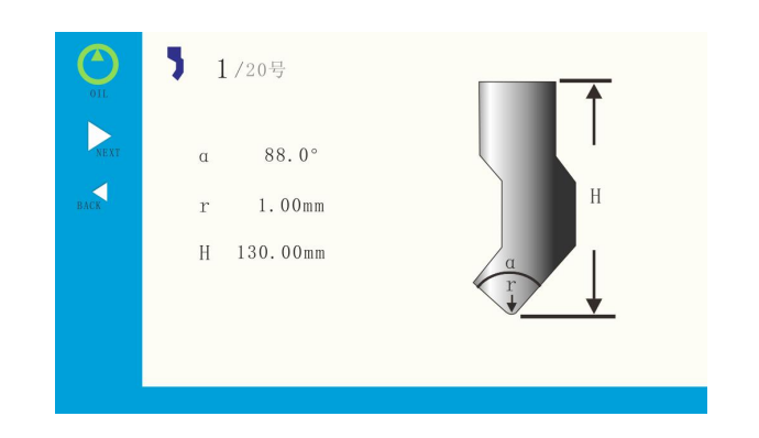
2.3.1 upper mold
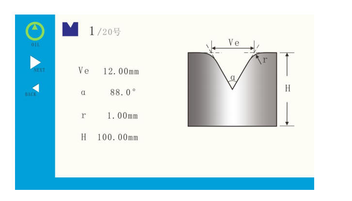
2.3.2 lower mold
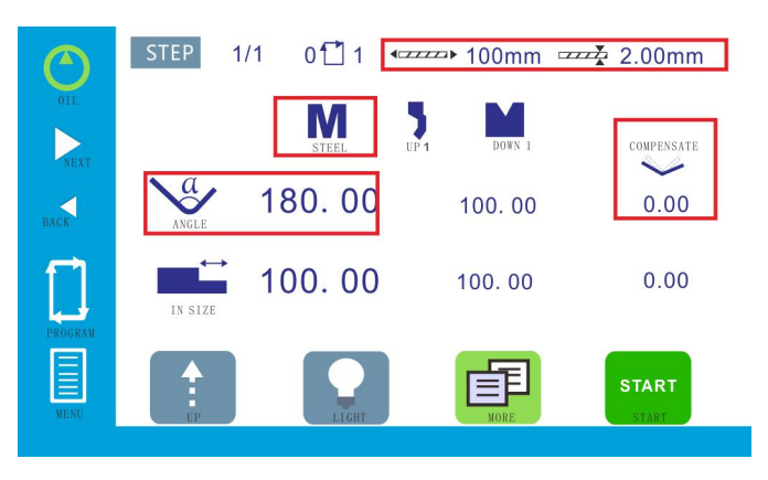
2.3.3 other parameter
The following red box:
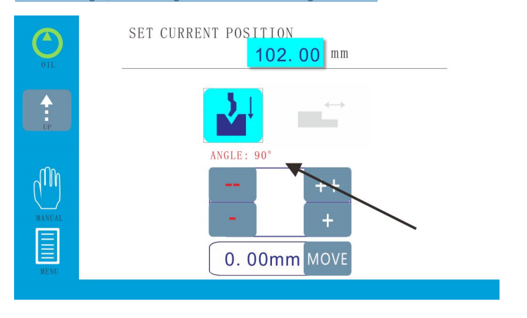
2.4 angle calibration
Set up the upper mold, lower mold, material, plate thickness and plate length, click the menu and enter manual debugging. Bend an Angle at will, then click the coordinate reference point and enter the password 1212. The actual Angle appears, enter the actual measured Angle, and the Angle is calibrated.The diagram below:
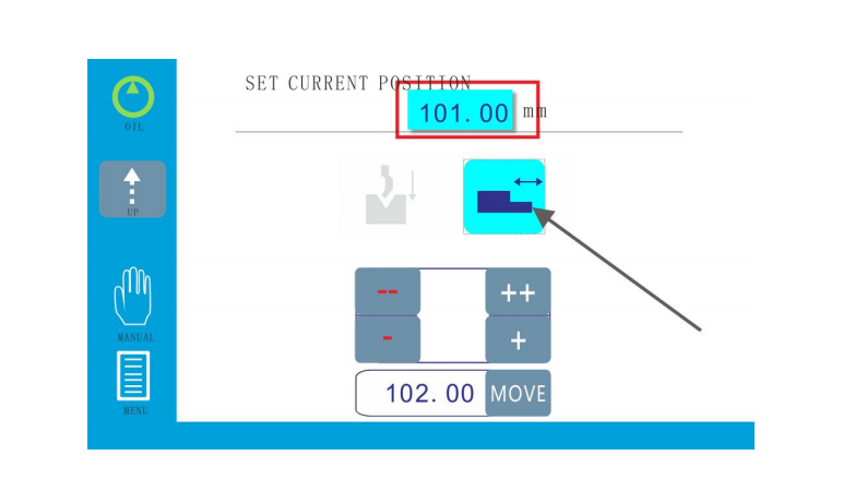
2.5 length of calibration
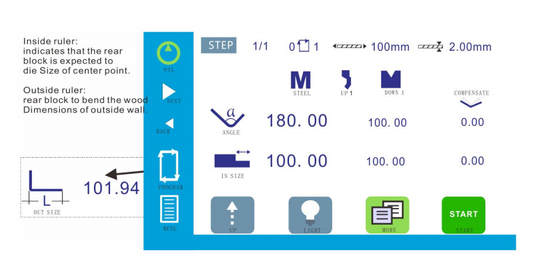
When the user uses the inner ruler to bend and inputs the size of the inner ruler as 100, if the actual measurement is 101, then click the menu into manual and change the coordinate reference point to 101. When the user uses the outside dimension to bend, if the actual outside dimension is 5, switch to the top of the outside dimension, enter 105, and then switch to the inside dimension. If the inside dimension is 103, click the menu into the manual and change the coordinate reference point to 103.
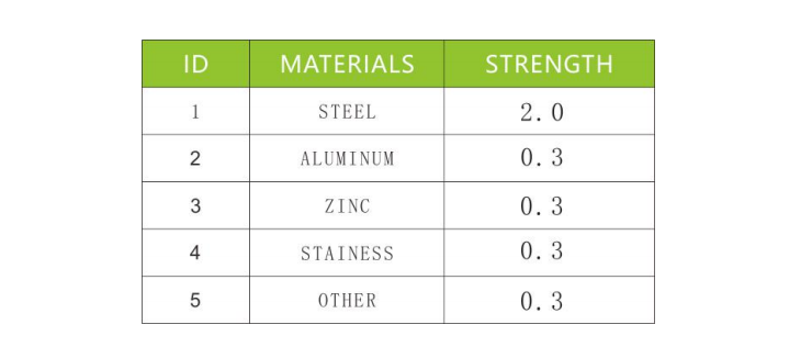
2.6 frame strength
When the user needs to bend the long board, because the long board has a larger rebound than the short board, so in the same Angle of folding, the long board should be pressed deeper than the short board, in order to correctly bend the required Angle.At this time, the frame strength of the material needs to be set, as shown in the figure below:
2.7 grid ruler
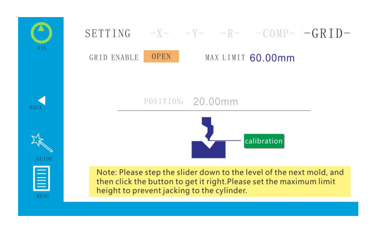
Before setting, please close the magnetic grid ruler first, step the upper mold and the lower mold to the flush position, then click the key to calibrate, the current position will automatically change to 0mm, then step on to stop the slider, check whether it will jack up the oil cylinder, and set the maximum limit position.
2.8 mechanical compensation
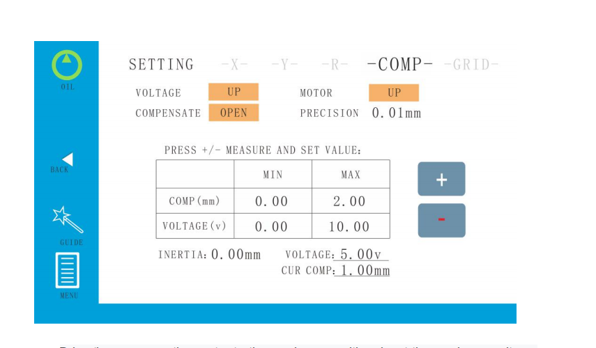
Drive the compensation motor to the maximum position, input the maximum voltage and the maximum height.Then the compensation motor is driven to the minimum position,input the minimum voltage and the minimum height.
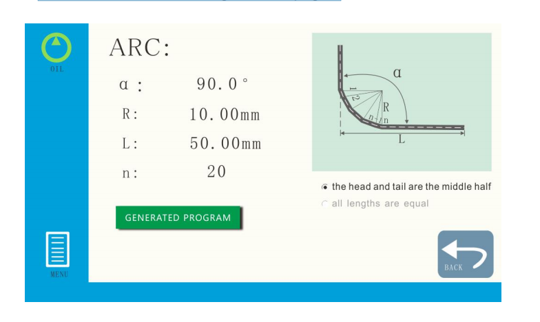
2.9 great arc
To set the size of the arc, click to generate the program
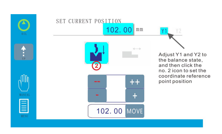
2.10 Y1-Y2 axis
3.user operation
3.1 single step programming
The user only needs one machining step when as follows
3.2 multi-step programming
Programming steps:
First set up the material, thickness, long plate and mold base, opening height and the speed change point, then set up the target size and bending Angle, set up after the firststep, click on add processing step by step number (see above), and then click the insert step sequence, at this point you can edit the second step, and so on, in the process of programming, will copy the programming of all parameters on the step。
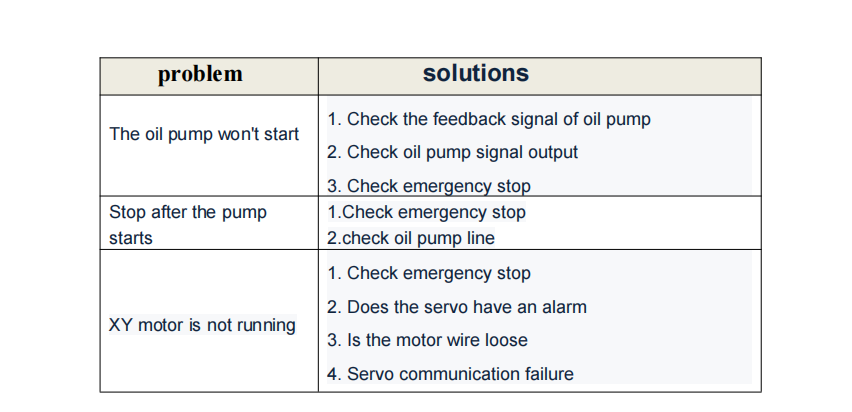
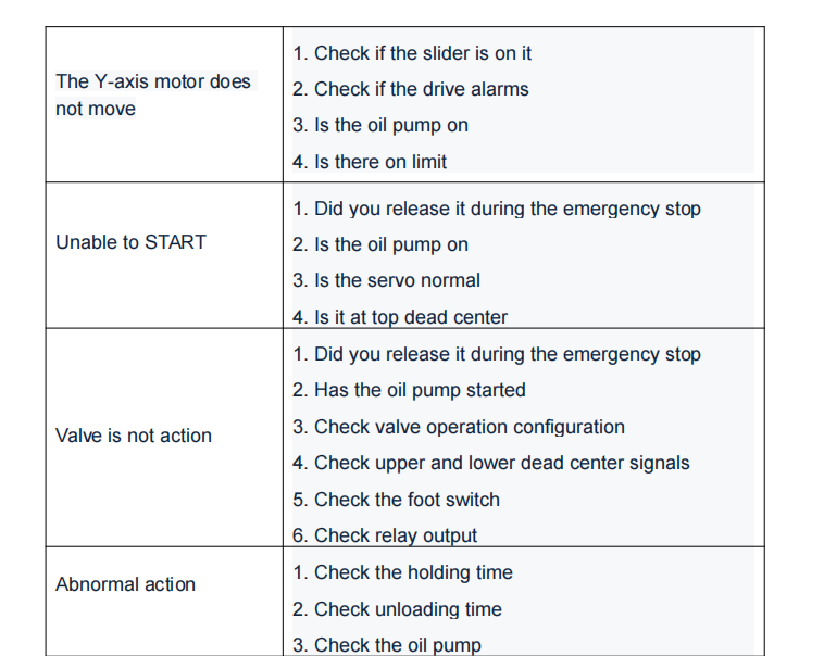
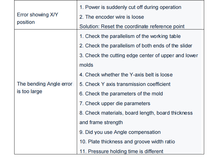
4.common problem