Skip to content

Manual operation E21 Controller ESTUN

Preface

This manual describes operation of E21 numerical control device and is meant for operators who are instructed for operation of the device. Operator shall read through this manual and know operation requirements before using this device.

Copy right is preserved by ESTUN. It is not allowed to add or delete part or all of the manual content without ESTUN’s consent. Do not use part or all of manual content for the third party’s design.
E21 device provides complete software control and has no mechanical protection device for operator or the tool machine. Therefore, in case of malfunction, machine tool must provide protection device for operator and external part of the machine tool. ESTUN is not responsible for any direct or indirect losses caused by normal or abnormal operation of the device.

ESTUN preserves the right to modifying this manual in the event of function adding or print error.

Part 1  – Operation Instruction

1.1 Basic operation procedure

Basic switch over and operation procedure of the device is shown in Figure 2-1.

Figure 2-1 Basic Operational Flow

Part 1  – Operation Instruction

1.2 Programming

The device has two programming methods, which are single-step programming and multi-step programming. User can set up programming according to actual demand.

1.2.1 Single-step programming

Caution: When the parameter X or Y displays  on the page, please do not enter the RUN page or Manual page, unless you have reset the teach function of X-axis or Y-axis.

Single-step programming is generally used for processing single step to finish work piece processing. When controller is power on, it will automatically enter single-step program page.

  • Operation steps

Step 1 After starting up, the device will enter setting up page of single-step program automatically, as shown in Figure 2-2.

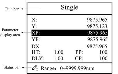
Figure 2-2 Single-step program setting page

Step 2 Press , select parameter which needs to be set up, press numerical key to input program value, press to complete input.

[Note] Parameter can only be set when Stop indicator is on.
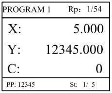
Step 3 Press , system will execute according to this program, as shown in Figure 2-3.

Figure 2-3 Single step operation page

  • Operation example

On single-step program page, program bending depth to 100.0mm, back gauge position to
80.00mm, retract distance to 50mm, concession waiting time to 2s, holding time to 3s, work
piece to 10.
Operation steps are shown in Table 2-2.

1.2.2 Multi-step programming

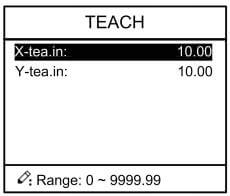
Caution: When the parameter X or Y display on the page, please do not enter the RUN page, unless you have reset the teach function of X-axis or Y-axis.

Multi-step program is used for processing single work piece of different processing steps, realize consecutive implementation of multi-steps, and improve processing efficiency.

  • Operation step

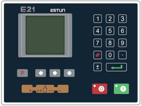
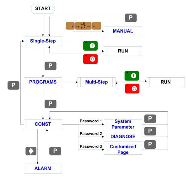
Step 1 Power on, the device displays the single-step parameter page automatically.
Step 2 Press  , switch to program manage page, as shown in Figure 2-4.

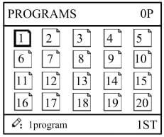
Figure 2-4 Program management page

Step 3 Press , select program serial number, or input program number directly, such as input “1”.

Step 4 Press , enter multi-step program setting page, as shown in Figure 2-5.

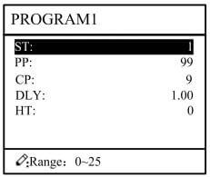
Figure 2-5 Multi-step

Step 5 Press  , select multi-step programming parameter which requires set up, input
setting up value, press , and the set up takes effect.
Step 6 In completion of set up, press  , enter step parameter set page, as shown in Figure 2-6.

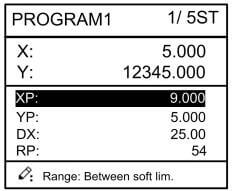
Figure 2-6 Step parameter set page

Step 7 Press , select step parameter that needs to be set up, input program value, press , and the setup takes effect.
Step 8 Press  to switch over between steps. If the current step is the first step, press  to enter the last page of step parameter setting; if the current step is the last one, press to enter the first page of step parameter setting.

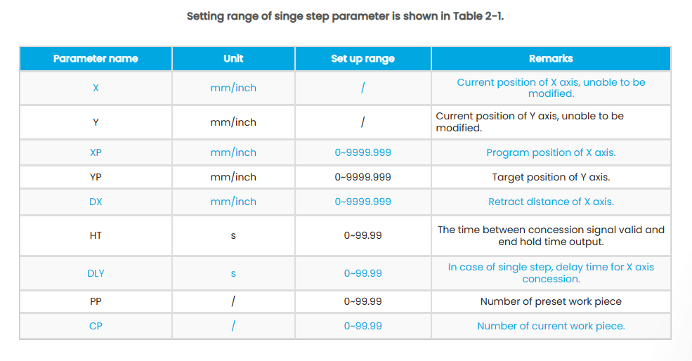
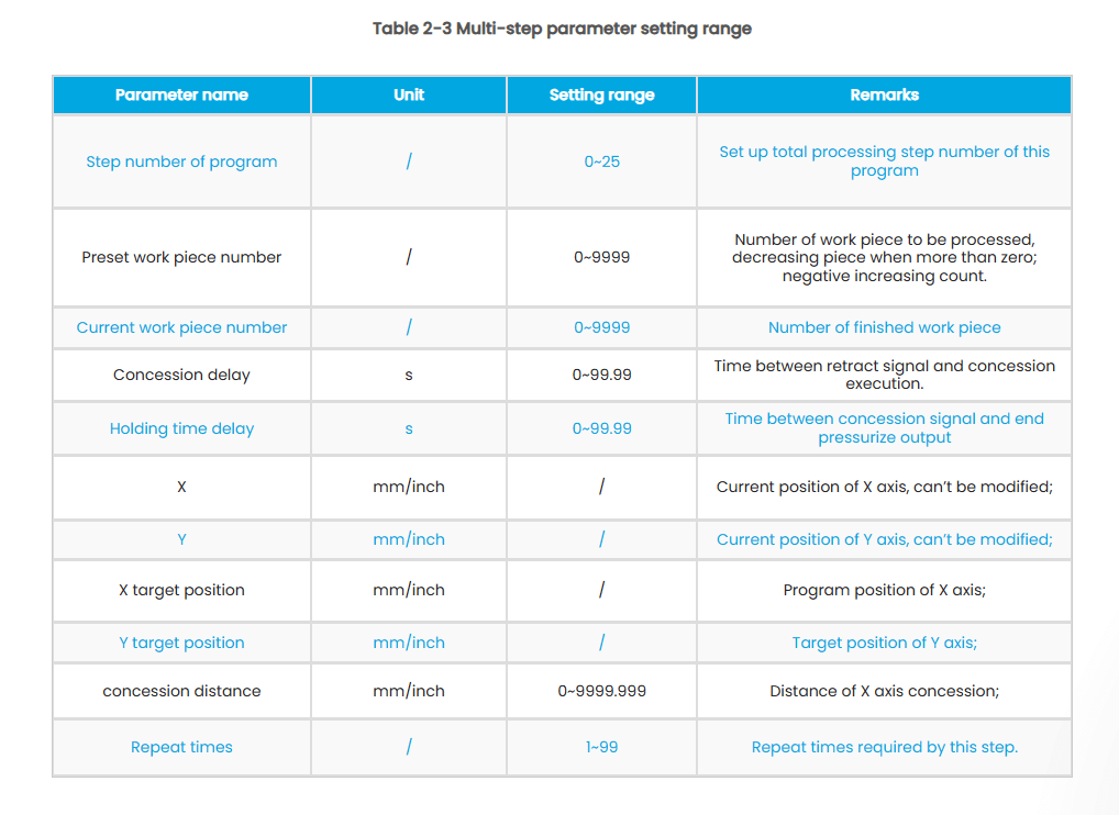
Multi-step parameter setting range is shown in Table 2-3.

Step 9 Press , system will operate according to this program, as shown in Figure 2-7.

Figure 2-7 Multi-step programming operation page

  • Operation example

[Background] One work piece requires processing 50 as shown below;

■ First bend: 50mm

■Second bend: 100mm

■Third bend: the other direction 300mm
[Analysis] according to work piece and technological conditions of machine tool

■First bend: X axis position is 50.0mm; Y axis position is 85.00mm, concession 50mm

■The second bend: X axis position is 100.0mm; Y axis position is 85.00mm, concession 50mm

■The third bend: X axis position is 300.0mm; Y axis position is 85.00mm, concession 50mm
Edit processing program of this work piece on No. 2 program.
Operation procedure is shown in Table 2-4.

<Note>

■ In completion of multi-step programming, return to start step before launching the system; otherwise, the program will start position processing at current step.

■ Press left and right direction key to circulate page turning and browsing among all step parameters.

■ Program can be called and revised again.

■In completion of processing all work pieces (50 in the example), system stops automatically. Restart directly will start another round of processing 50 work pieces.

1.3 Parameter setting

User can setup all parameters required for normal operation of the system, including system parameter, X axis parameter and Y axis parameter.
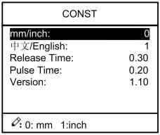
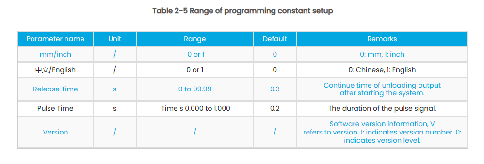
Step 1 On program management page, press  to enter programming constant page, as shown in Figure 2-8. On this page, programming constant can be set.
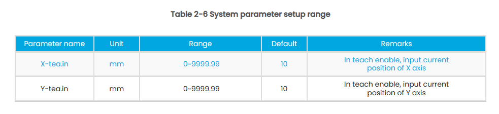
Figure 2-8 Programming constant page

Range of programming constant setup is shown in Table 2-5.

Step 2 Input password “1212”, press to enter the Teach Page, as shown in Figure 2-9.

Figure 2-9 System parameter setting page

Step up parameter, parameter setup range is shown in Table 2-6.

<How to Teach>: You can directly measure the positions of slider and back gauge. If the measurement is difficult, you can program and operate any one process, and then measure the accomplished workpiece.

Step 3 Press  , return to programming constant page.
—-End

1.4 Manual adjustment

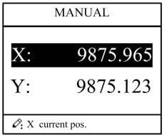
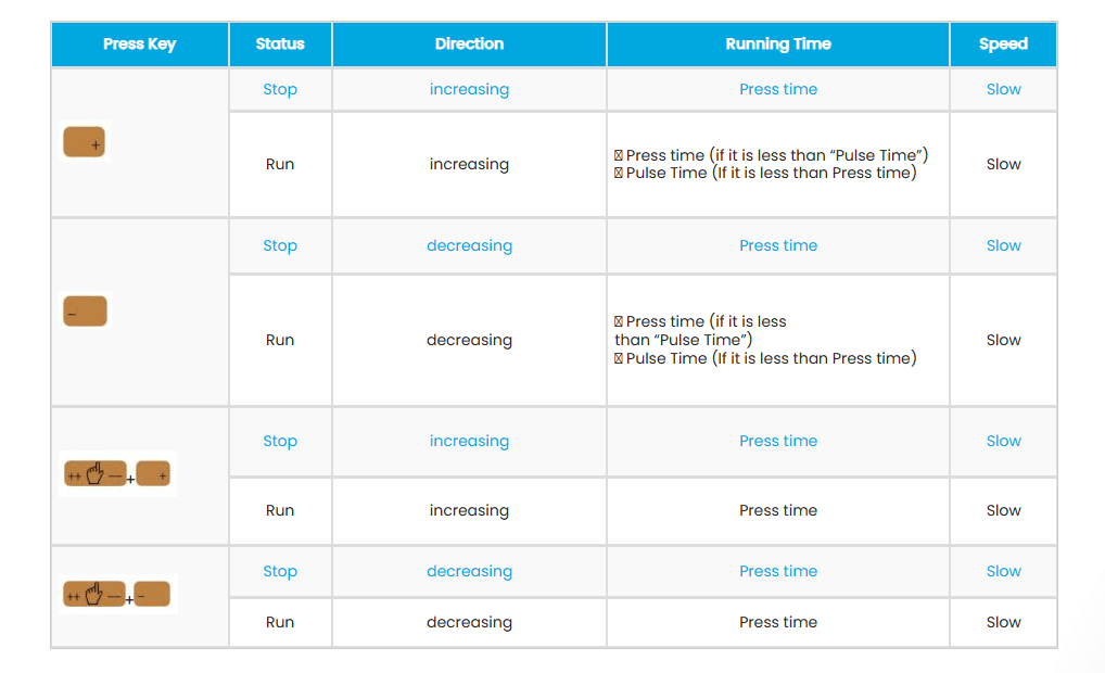
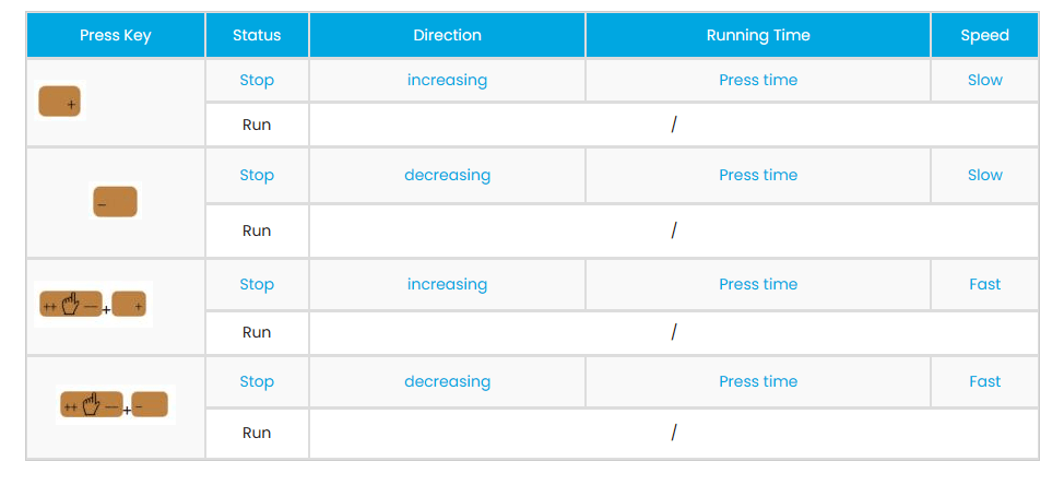
In single-step mode, axis movement can be controlled by pressing key manually. This method helps user to adjust machine tool and work piece.
Step 1 On single step parameter setup page, press or  to enter manual page, as shown in Figure 2-10.

Figure 2-10 Manual page

Step 2 According to your actual requirement, following the above table to adjust the position of the axis. – If the drive mode of the corresponding axis is common motor:

<Note>: When the system is on run status, the operation of manual adjustment is just valid for the X-axis.

– If the drive mode of the corresponding axis is frequency:

Step 3 Press return to single step parameter setting page.
—-End

Part2 – Alarm

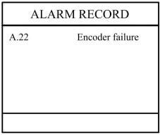
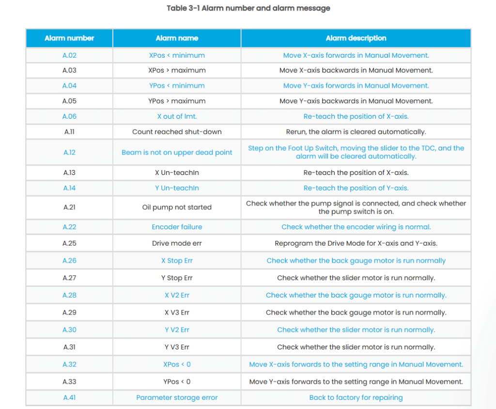
The device can detect internal or external abnormity automatically and send out alarm prompt. Alarm message is available on alarm list.
Step 1 On programming management page, press  to enter programming constant page.
Step 2 On programming constant page, press  to enter “Alarm history” page to view all alarm history.
As shown in Figure 3-1, the latest 6 alarms, alarm number and causes can be viewed on this page

Figure 3-1 Alarm history page

Alarm history and message is shown in Table 3-1.

Appendix Common Fault and Troubleshooting

2.1 Product introduction

This product is equipped with press brake machine dedicated numerical control device which is applicable to various users. On the basis of ensuring work precision, the cost of numerical control bending machine is reduced significantly.

Features of this product are listed below:

■ Positioning control of back gauge.

■ Intelligent positioning control.

■ Unilateral and bidirectional positioning which eliminates spindle clearance effectively.

■Retract functions.

■ Automatic reference searching.

■One-key parameter backup and restore.

■Fast position indexing.

■ 40 programs storage space, each program has 25 steps.

■Power-off protection.

2.2 Operation panel

Operation panel is shown in Figure 1-1.

Figure 1-1 Operation panel

Functions of panel keys are described in Table 1-1.

2.3 Displayer

E21 numerical control device adopts 160*160 dot matrix LCD displayer. The display area is shown in Figure 1-2.

Figure 1-2 Display area

■ Title bar: display relevant information of current page, such as its name, etc.

■ Parameter display area: display parameter name, parameter value and system information.

■ Status bar: display area of input information and prompt message, etc.

The paraphrases of shortening on this page are as shown in Table 1-2.

About Us

Durmapress specializes in designing, manufacturing and selling various metal processing equipment, including bending machines, shears, punches, laser cutting machines, etc. The company was founded in 2000. With years of experience and technology accumulation. DurmaPress has become one of the well-known brands in China's metal processing machinery industry.

Contact Us

Recent Posts

Categories

Follow Us

Weekly New Video

Contact us for more information

If you have any information about our products, please contact us and we will reply within 24 hours.

ru_RURussian
WeCreativez WhatsApp Support
Our customer support team is here to answer your questions. Ask us anything!
👋 Hi, how can I help?