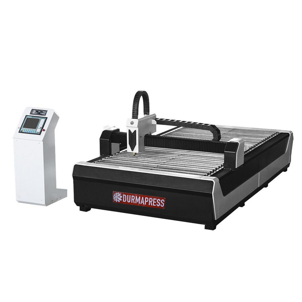
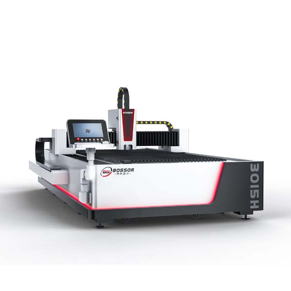
Many customers in the purchase of CNC cutting machine, will always be concerned about the CNC cutting machine cutting accuracy? This paper focuses on the NC cutting machine walking precision adjustment method. First let's introduce the CNC cutting machine precision test method, cutting machine precision before delivery can ensure to do 0.01mm/ step, accuracy error in ±0.5mm or so, the error was higher than the cutting machine itself several times, but the error is not formed by the equipment XC3BL itself, But in the process of cutting the thickness of the steel plate, technology, cutting mouth, fire and other processes formed.
After the device ends, a scribing installation will be installed on the cutting mouth of the CNC cutting machine. After the scribing installation, an imitation cutting graph will be drawn, and the imitation graph will be a square of 1m. Built-in a circle with a diameter of 1m, and draw diagonal lines on its four corners. After drawing, use the measuring tool to measure whether the circle drawn is tangent to the four sides of the square. Whether the diagonal length of the square can be √2 (the data obtained by taking the square root is about: 1.41m), the central axis of the circle should bisect the sides of the square, and the interval between the intersection point of the central axis and the two sides of the square and the intersection point of the two sides of the square should be 0.5m. The cutting precision of the equipment can be determined by measuring the interval between the diagonal line and the intersection point.
1) Detailed steps for adjusting pulse equivalent (walking accuracy)
1. Select the "Manual" function.
2. Select the "Inching" function from the manual function, press "3", and enter the inching increment (example: 1000mm).
3. Make an obvious mark on the rail corresponding to a point on the big car. And let the cart on the marked axis to move a dot increment (e.g. 1000mm).
4, corresponding to the point of the big car, do another sign on the rail, and measure whether the two distances are moving incremental distance (such as 1000mm).
5. If the actual distance traveled is larger than the point-motion increment, it means that the pulse equivalent is smaller; otherwise, it means that the pulse equivalent is larger.
6. Modify the pulse equivalent. Under the main screen, select "Parameter" setting, then select "System" parameter, modify the corresponding gear molecular value, and press "Save". (Reminder: 1mm corresponds to about 2.5 gear molecules at the point of 1000mm. And so on, if the X axis of the machine tool goes 1mm more, the X gear molecules should be added about 2.5. The Y axis is similar.)
7. Repeat the third step until the distance is equal to the point increment.
8. Use the same method to measure the pulse equivalent of Y axis and modify it.
9. Write the measured pulse equivalent in an obvious location that is not easily erased, such as inside the rear door of the case, for future recovery.
Above, we have explained the adjustment accuracy in detail. Let's move on to the following calibration test issues.
As the machine in use for a period of time, the longitudinal electric machine on both sides appear slight drop phenomenon. Therefore, it will lead to the Angle deviation between the beam and the guide rail, and make the beam tilt. In this regard, we have to make some slight adjustments to the machine to ensure that the machine can be restored to the normal cutting state. The specific operation steps are as follows:
1. First of all, the inclination direction of the beam is measured by cutting the workpiece. This step is very important.
2. As shown in the figure above, diagonal 1 is longer than diagonal 2. (The position of the main bracket shall prevail) Therefore, it can be known that the tilt direction of the beam is "↑". If diagonal 1 is less than diagonal 2. Then the beam tilt direction is "↓".
3, by calculating the "?" The value of the. Suppose "?" = "5.5"
4. Turn it off.
5. Unplug the 3-core aviation plug connected between the longitudinal motor on the side of the system box and the system box, so that only the auxiliary bracket can move during calibration.
6. Loosen the 4 bolts on the side of the system box that are used to fasten the beam and the main support.
7. Turn on the machine.
8. Manual, point moving, press "3" to input the distance needed to point moving, input the value "5.5" just calculated, press the direction key "↓" (the opposite direction of the machine beam tilt direction) to adjust the auxiliary bracket back to the correct position.
9. Turn it off.
10. Restore the 3-core aerial plug connected between the longitudinal motor on this side of the system box and the system box.
11. Fasten the connecting bolt between the beam and the main bracket.
12. Calibration completed.
About the precision of CNC cutting machine equipment, is a very need to pay attention to a standard, science articles to help us learn to understand the habits of equipment, operation, but also with our factory engineers the whole teaching.

