About Us
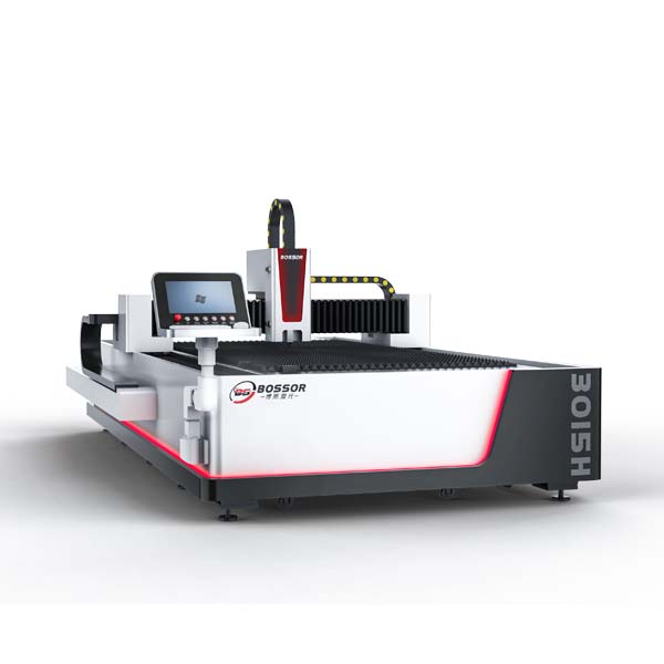
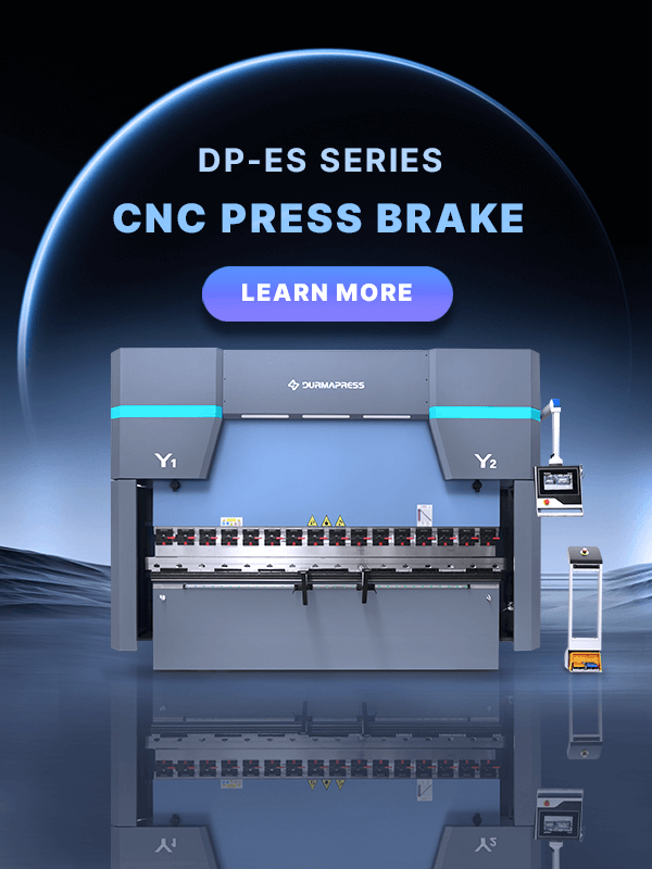
Durmapress specializes in designing, manufacturing, and selling various metal processing equipment, including bending machines, shears, punches, and laser cutting machines. The company was founded in 2014, with years of experience and technology accumulation. DurmaPress has become one of the well-known brands in China's metal processing machinery industry.

Contact Us
Recent Posts

Categories
Follow Us
Weekly New Video
Selecting the best press brake tooling is crucial for both accuracy and efficiency. This guide redefines what “best” truly means—beyond brands—by explaining tooling types and systems, and introducing a five-step decision-making framework to match materials and machines. With the right choice and maintenance, tooling can evolve from a consumable item into a valuable asset that enhances manufacturing performance.
For a comprehensive overview of press brake tooling types and selection strategies, see our Press Brake Tooling: Complete Guide to Types & Selection.
Defining “Best”: Beyond Brand, Toward an Application-Driven Excellence Framework
Choosing the “best” tooling does not mean buying the most famous brand or the most expensive option—it means building a framework of excellence driven by actual application requirements. “Best” is a relative and dynamic concept, determined by the optimal match between material characteristics, process demands, and machine parameters.
Selection Based on Material Characteristics
High-Hardness Materials (e.g., Stainless Steel, High-Strength Steel)
For press operations involving hard materials, the tooling must exhibit outstanding wear resistance and deformation strength to maintain its shape and precision under long-term high pressure. Key performance indicators include hardness, wear resistance, and compressive strength. Recommended materials: Cr12MoV, SKD11 high-hardness alloy steels.
High-Toughness Materials (e.g., Mild Steel, Spring Steel)
When processing tough materials, tooling must provide superior impact resistance to prevent cracking or chipping caused by repeated impact. Key indicators: toughness and fatigue strength. Recommended materials: 42CrMo, H13 hot-work tool steels—offering an excellent balance of strength and ductility for extended tool life.
High-Ductility Materials (e.g., Aluminum, Copper)
For soft, ductile materials, tooling must feature an extremely smooth surface to minimize friction and prevent scratching, ensuring excellent part appearance. Key indicators: surface finish and anti-adhesion properties. Recommended materials: CrWMn, S136 stainless steel, mirror-polished to significantly improve forming quality.
Selection Based on Process Requirements
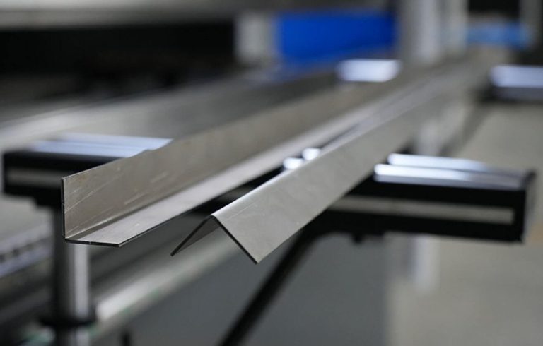
Different bending methods require specific geometric configurations, strength levels, and surface finishes. For example, during radius bending, the tooling must have excellent anti-adhesion performance to prevent surface impressions during stretching. In acute-angle bending, the punch tip must possess extremely high hardness and fracture resistance to withstand localized high pressure.
Compatibility with Press Brake Parameters
Tooling must fully match the machine’s tonnage, bed length, throat depth, and open height. Mismatched tooling can cause equipment overload, accelerated wear, or in severe cases, tool breakage and permanent machine damage. Thus, the real definition of “best” tooling is a solution that provides sustained, high-precision output with maximum efficiency, stability, and safety under specific working conditions, while minimizing total cost of ownership (TCO).
Five-Step Decision Framework: A Practical Path to the Perfect Tool
Tooling selection should not rely on intuition or experience—it requires a disciplined, replicable, and scientific process. The following five-step framework will guide you from material analysis to long-term investment evaluation, eliminating guesswork and maximizing value at every decision.
Step 1: In-Depth Material Analysis
Every design begins with material understanding. Before choosing any tool, analyze your material like a materials scientist by identifying the four fundamental “genetic markers” that determine bending success.
Tensile Strength – The Key to Tonnage Requirements
Tensile strength determines the bending force required. Advanced high-strength steels (AHSS) can have several times the tensile strength of mild steel, requiring higher bending forces and tougher, more wear-resistant tools. Ignoring tensile strength and relying only on thickness is the top cause of premature tool wear or failure. Ensure your tonnage chart includes tensile strength as a core input variable.
Yield Strength & Springback – The Angle Control Factor
Yield strength defines how much the material “remembers” its original shape after bending—i.e., springback. Hard materials like stainless steel may spring back 2–3°, while soft aluminum has almost none. To achieve accurate 90° bends in high-springback materials, use a slightly sharper punch (88° or even 85°) to compensate. Ignoring springback leads to endless re-adjustments and wasted setup time.
Ductility & Minimum Bend Radius – The Crack Prevention Rule
Ductility determines the minimum internal bend radius before cracking occurs. A common guideline suggests that the ideal internal radius equals material thickness. Using too sharp a punch to force smaller radii overstretches the outer surface, causing cracks. The punch tip radius must therefore be equal to or greater than the material’s minimum bend radius—a non-negotiable principle for product integrity.
Surface Condition – The Guardian of Aesthetics
Surface coatings such as galvanized, painted, anodized, or mirror finishes directly affect friction between the sheet and tooling. When bending mirror stainless steel or anodized aluminum, even tiny defects can cause scratches. Use highly polished tools (Ra < 0.2 μm), low-friction coatings such as TiN, or protective film tooling to maintain flawless surface quality.
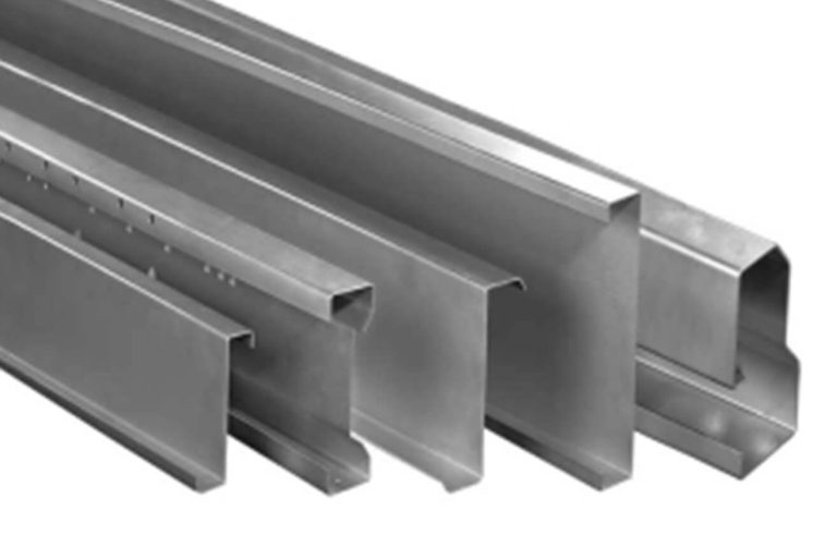
Step 2: Define Bending Geometry Accurately
After understanding material properties, translate your design geometry into tooling parameters. Focus on the three core bending dimensions while mastering the “8× rule.”
Bend Angle & Process Type
Decide whether you need 90°, acute, or obtuse bends. This determines whether you use air bending, bottoming, or coining, and defines the required punch and die angles.
Controlling Internal Radius
In air bending, the internal radius depends mainly on the die opening (V-width), not just punch tip radius: internal radius ≈ V-opening × 0.16. Choosing different V-openings allows precise radius control—one of modern bending’s greatest advantages.
The “8× Rule” Reconsidered
Common rule: V-opening = material thickness × 8, but real experts know when to adjust. For thick plate (>10 mm): use 10–12× for more contact and stress distribution. For soft metals such as aluminum: use about 6× for smaller radii. For tight-radius bends: use narrower dies but recalculate tonnage to stay within safe limits.
Minimum Flange Length
Flange length must be at least 70% of the V-opening to rest properly on die shoulders. Shorter flanges fall into the die, preventing proper forming—an essential design consideration.
Common Punch Types
The standard punch is the most versatile and widely used punch type. It has a thick body that can withstand high bending forces, and its slightly concave side profile allows for shorter flange formation. It is the right starting point for most general bending applications with mild steel and similar materials.
1. Standard/General Punch
The standard punch is the most versatile and widely used punch type. It has a thick body that can withstand high bending forces, and its slightly concave side profile allows for shorter flange formation. It is the right starting point for most general bending applications with mild steel and similar materials.
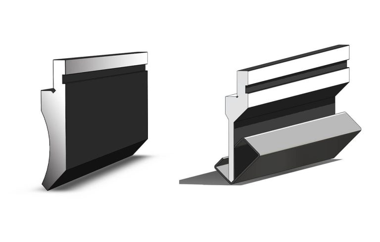
2. Gooseneck Punch
The gooseneck punch is designed with a curved neck that creates clearance for the workpiece flanges to pass through the centerline of the bend. This makes it essential for bending U-shaped profiles, box sections, and any part where previously formed flanges would collide with a straight punch body. It is one of the most universally useful punch shapes in sheet metal fabrication. However, because of its open neck geometry, the gooseneck punch has a lower tonnage capacity than a standard punch of the same height. If you see a gooseneck punch rated above 50 tons per meter, verify this figure directly with the manufacturer before relying on it.
3. Acute Punch
The acute punch has a sharp tip designed for bending angles of 35 degrees or less. It is also commonly used as a pre-bending tool in hemming and flattening operations, where the first pass creates a sharp acute bend before a second pass flattens the flange completely.
4. Narrow/Sword Punch
The narrow punch has a uniformly thin profile throughout its entire height. This allows it to enter tight spaces where other punches cannot fit, making it particularly useful for closing square or rectangular box profiles where the punch must fit between two closely spaced flanges.
5. Radius Punch
The radius punch has a rounded tip larger than R3, designed to form large-radius bends in a single pass. These punches are available in solid form or as a universal holder with interchangeable radius inserts, which is a more flexible and cost-effective solution when multiple radii are needed. A larger tip radius also helps reduce tip wear when working with thick materials.
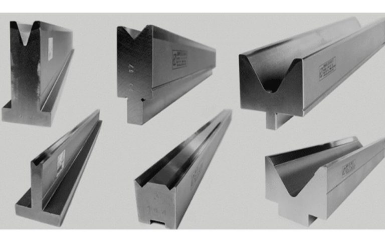
Common Die Types
1. V Die
The single V die is the most common and straightforward option, featuring one V-groove centered on the die body. It is ideal for stable production runs with a consistent material thickness and is the standard choice for all large V openings above approximately V50.
2. 2V and 4V Die
Multi-opening dies allow you to cover multiple material thicknesses with a single die body by rotating the die to the appropriate groove. A 4V die with standard openings is widely considered the ideal starter package for new press brakes, offering enough versatility to handle a broad range of thicknesses without requiring multiple die changes. Many press brake manufacturers include a general punch and a 4V die as the default tooling set with new machines for this reason.
3. Multi-V Die
Multi-V dies feature more than four openings and are typically manufactured to match the full bending length of the machine. They are most common on older machines and heavy-tonnage equipment where changing individual dies is physically difficult and time-consuming. On modern machines with proper die holders, multi-V dies have largely been replaced by sectioned single or 4V dies due to their lower production cost and greater flexibility.
4. Spring Die
Spring dies are purpose-built for hemming and flattening operations. They feature two working surfaces: one for the initial acute pre-bend and one flat surface for the final flattening stroke. These dies are not recommended for daily standard bending work because repeated use for standard bends accelerates spring wear and degrades repeatability.
5. Polyurethane Die
Polyurethane dies are used in two main scenarios. First, when surface marking must be completely avoided, the elastic material provides a soft contact surface that will not scratch or mar sensitive finishes. Second, for large-radius bending, the controlled elastic deformation of polyurethane allows the punch to form smooth large-radius curves that would require expensive dedicated radius tooling in standard metal dies. The main limitation of polyurethane dies is wear: they degrade over time, which gradually reduces the repeatability of bends in continuous production.
Step 3: Match Tooling with Machine Parameters
1.Clamping system
Different press brake manufacturers use different tooling clamping systems, and tools are not interchangeable across systems without adapters. The most widely used system globally is the Promecam/Euro system, which is standard on the vast majority of Asian-made machines and many European brands. Other major systems include Trumpf/WILA, Bystronic/Beyeler, and LVD. Even within the same system, there are variations between older and newer generations. Before purchasing any tooling, confirm exactly which clamping system your machine uses, including the punch tang geometry and die seating geometry.
2.Tonnage
You need to know two things: the total declared tonnage of your machine, and the tonnage per meter of bending length. These are not the same. A 220-ton machine with a 3-meter table delivers approximately 73 tons per meter under standard distribution. More importantly, confirm whether your machine allows concentrated tonnage for short bending lengths, as some machines limit you strictly to the distributed figure. This matters when bending short but thick parts.
3.Daylight and bending length
Daylight is the maximum distance between the upper beam and the lower table with no tooling installed. For most standard parts this is not a concern, but for deep boxes or tall profiles, you must verify that the combined height of your punch, die, and workpiece does not exceed the available daylight. Bending length defines the maximum length of tooling that can be installed. Always match your tooling length to the actual bend length required.
Bending Sequence Verification
Selecting individual punches and dies is only part of the process. You also need to ensure the complete set of tooling works through every step of your bending sequence without collision or interference.
1. Start with the last bend
Always begin your tooling study by identifying the last bend in the sequence. If the punch cannot safely complete the final bend without colliding with the already-formed part geometry, no amount of work on the earlier bends matters. Confirm the final bend is achievable first, then work backward through the sequence.
2. Apply the centerline rule
Check whether any part of the workpiece crosses the punch centerline during any bend in the sequence. If the flange passes through or behind the centerline, a gooseneck punch is required for that step. If no part of the workpiece crosses the centerline and the nearest flange is more than 10 to 15mm away from the punch body, most standard punch shapes can be used.
3. Check die clearance for return bends
For bends in the opposite direction to previously formed flanges, or for Z-shaped sections, check that the workpiece flanges can be positioned over the die without collision. The general rule is that the distance from the bend line to the nearest obstacle on the part must be at least half the total width of the die being used. If this clearance is not available, a narrower die or a different bending sequence may be required.
4. Consider springback in collision checks
Most bending simulations, including those on CNC press brake controls, display part geometry at exactly 90 degrees without accounting for the actual overbend angle used to compensate for springback. In reality, when you bend to 87 or 88 degrees, the flange end position is slightly different from what the simulation shows at 90 degrees. If your clearance between tooling and part is very tight, this small positional difference can cause a real-world collision that the simulation does not predict. Always leave a small additional margin when clearances are tight.
Step 4: Evaluate Tool Material, Hardness & Coating
Tool quality depends on base material, heat treatment, and surface coating.
Material Selection – Balancing Toughness & Wear Resistance
42CrMo: versatile and economical; after heat treatment reaches HRC 47±2, offering excellent balance of toughness and wear resistance.
Cr12MoV: the wear specialist. High-carbon, high-chrome steel reaching up to HRC 60 for stainless or high-volume production.
Carbide: the ultimate champion. Extremely hard and durable but expensive and brittle—ideal for high-precision applications.
The Hardness-Toughness Paradox
Hardness provides wear resistance, but too much sacrifices toughness, leading to brittle fractures. Ideal hardness must match the material’s strength—durable under dynamic loads without cracking.
Coatings – The Performance Multiplier
TiN (Titanium Nitride): classic golden coating, boosts hardness, reduces friction, and prevents sticking—perfect for aluminum and stainless steel.
DLC (Diamond-Like Carbon): ultra-low friction and high hardness, ideal for nonferrous metals to avoid scratching and sticking.
Step 5: Balance Initial Cost and Long-Term Value (LTV)
Shift perspective—from a buyer’s cost mindset to an investor’s value mindset. The cheapest tooling often becomes the most expensive during production. Evaluate Total Cost of Ownership (TCO) and Long-Term Value (LTV) rather than initial price.
TCO/LTV Evaluation Framework
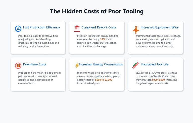
Setup Time: low-precision tools require multiple test bends, adding over 30 minutes of downtime per setup. High-end tools offer plug-and-play precision, reducing setup time from hours to minutes.
Scrap & Rework Rate: low-grade tools cause unstable angles and scratches, leading to 5–10% scrap. High-end tools reduce waste below 1%, boosting profit and yield.
Tool Life: cheap tools wear quickly (few thousand cycles). Premium tools last hundreds of thousands, lowering lifetime cost.
Machine Wear: poor tool design causes uneven stress, accelerating wear and shortening maintenance intervals by 20%. High-quality tools distribute load evenly, protecting million-dollar machines.
Safety: low-grade tools risk cracking and injuring operators; premium tools ensure fail-safe performance and workplace safety.
By applying this five-step framework, you elevate tooling selection from a purchasing task to a data-driven strategic decision—optimizing production flow, minimizing hidden costs, and creating a durable competitive edge.
Common Tooling Selection Mistakes to Avoid
1. Ignoring clamping system
The most basic mistake is purchasing tooling without confirming compatibility with the machine’s clamping system. Even correctly shaped tools cannot be used safely if the shank does not match the tool holders.
2. Overlooking springback
Selecting a 90° punch for a 90° bend does not guarantee accuracy, as air bending always involves springback. Tooling angle must be selected according to material properties, with compensation built into the bending program.
3. Using a die opening that is too narrow
A narrower-than-recommended die opening increases bending force significantly and raises the risk of cracking, especially in harder materials. Required tonnage must always be calculated before selection.
4. Exceeding tonnage on gooseneck or horn sections
areas have reduced structural strength compared to standard punch bodies. Applying full rated tonnage to a gooseneck punch or to the horn sections of a box bending punch is one of the most common causes of punch deformation in production.
5. Buying many tools instead of finding one universal solution
For stable production with a defined set of parts, investing in one well-chosen punch that covers all your bending needs is almost always more cost-effective than maintaining a large inventory of specialized tools. Every additional tool change in the production cycle costs time, and over a full production year that time adds up significantly.
Conclusion
Our exploration of the “best press brake tooling” goes beyond brands or models. It builds a strategic enterprise-level framework, redefining tooling as a core asset balancing accuracy, efficiency, and cost—not a consumable. By understanding tooling types—from punches and dies to clamping systems—and following the five-step process covering material analysis, bending geometry, machine compatibility, material and coating evaluation, and cost-value balance, manufacturers can achieve sustained excellence. Proper installation, preventive maintenance, and troubleshooting protect your assets, ensuring long life and consistent quality. This holistic approach transforms tooling selection into a strategic pillar of manufacturing excellence, shifting focus from buying tools to investing in production assets. For expert consultation to guide your tooling strategy and maximize ROI, contact us today.