About Us
Learn what the K factor in sheet metal bending is, how to calculate it, typical values, and how it affects press brake bend allowance and flat pattern accuracy.


Contact Us
Recent Posts

Categories
Follow Us
Weekly New Video
Bending sheet metal accurately is essential in modern manufacturing. One key parameter engineers and press brake operators must understand is the K factor in sheet metal bending. It determines how the material stretches during bending and directly affects bend allowance, flat pattern accuracy, and production efficiency.
This guide explains K Factor in detail, provides formulas, typical values, practical examples, and best practices to improve bending precision.

What Is the K Factor in Sheet Metal Bending?
The K factor is a ratio that defines the position of the neutral axis during a bend relative to the material thickness:
Formula:
K=t/T
t = distance from the neutral axis to the inner surface of the material
T = material thickness
Neutral Axis Explained
When sheet metal bends, the inside layer compresses while the outside stretches. Somewhere between, there is a neutral axis that experiences no length change. The K factor represents the relative location of this axis, which is crucial for calculating bend allowance accurately.
Why K Factor Matters in Press Brake Bending
Using the correct K factor is critical for:
Accurate Bend Allowance Calculation
Bend allowance (BA) determines the exact flat length of the sheet before bending.
Using the wrong K factor leads to dimensional errors and costly scrap.
Reducing Trial and Error
Correct K factor reduces repeated test bends in production.
Improves material utilization and lowers scrap rates.
Optimizing CNC Programming
CNC press brakes rely on precise BA and K factor values to produce consistent parts.
How to Calculate K Factor and Bend Allowance
The Bend Allowance (BA) can be calculated using the formula:
BA=[π×Bend Angle×(R+K×T)]/180
Where:
- BA = Bend Allowance
- R = Inside Bend Radius
- T = Material Thickness
- K = K Factor
- Bend Angle in degrees
Example Calculation
Material: Mild Steel
Thickness (T): 2 mm
Bend Radius (R): 2 mm
Bend Angle: 90°
K Factor: 0.33
BA=[3.1416×90×(2+0.33×2)]/180=3.66
This means the sheet must allow an additional 3.66 mm along the bend to achieve accurate dimensions.Check our CNC press brake solutions for precise bending.
Typical K Factor Values for Different Materials
Different materials have different K factors due to elasticity, thickness, and bending properties. A typical reference table:
| Material | Typical K Factor |
|---|---|
| Mild Steel | 0.30 – 0.45 |
| Stainless Steel | 0.35 – 0.50 |
| Aluminum | 0.33 – 0.45 |
| Copper | 0.40 – 0.50 |
Tip: Always verify with sample bends; the “typical value” is only a starting point.
Factors Affecting K Factor
Several factors influence the K factor and must be considered during bend calculations:
Material Type
Different metals stretch differently under bending.
Sheet Thickness
Thicker materials shift the neutral axis outward.
Bend Radius
Smaller inside radii increase stretching on the outer fibers.
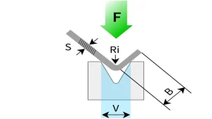
Tooling & Press Brake Setup
V-die opening and punch radius affect how the sheet bends.
CNC press brake precision also influences the final part.

Best Practices for Accurate Bending
CAD Software Verification
SolidWorks, AutoCAD, and other CAD software can calculate K factor automatically for sheet metal parts.
Default K factor values in software often range 0.33–0.5 depending on material.
Bend Test Method
Cut a sample piece.
Perform the bend.
Measure the bend allowance.
Calculate the actual K factor.
Check Tooling
Verify punch radius and V-die width for consistency.
Ensure CNC press brake settings match calculated BA.
K Factor vs Bend Allowance vs Bend Deduction
Understanding these related terms helps avoid confusion:
| Term | Meaning |
|---|---|
| K Factor | Neutral axis ratio within material thickness |
| Bend Allowance | Arc length along the neutral axis |
| Bend Deduction | Amount to subtract from total flat length to account for bending |
Common Mistakes
- Using the same K factor for all materials
- Ignoring tooling differences
- Assuming bend radius without verification
Avoiding these mistakes ensures higher accuracy and lower scrap rates.
Conclusion
The K factor in sheet metal bending is essential for calculating bend allowance and achieving precise, repeatable bends. Using the correct K factor reduces errors, minimizes scrap, and improves manufacturing efficiency. For CNC press brake operations, verifying K factor through CAD or sample testing is highly recommended.
FAQ
Q1: What is the typical K factor for sheet metal?
Varies by material: mild steel 0.3–0.45, stainless 0.35–0.50, aluminum 0.33–0.45.
Q2: How do you calculate K factor in sheet metal bending?
Measure the distance from the neutral axis to the inner surface and divide by material thickness: K = t / T.
Q3: Is K factor always 0.33?
No, 0.33 is a common default, but actual K factor depends on material, thickness, bend radius, and tooling.
Q4: What affects the K factor in press brake bending?
Material type, thickness, bend radius, tooling, and press brake setup.
Q5: How does K factor affect flat pattern calculation?
It determines the bend allowance, which affects the total flat length of the sheet.