About Us
Learn the minimum bend radius for sheet metal with charts, formulas, and engineering tips. Avoid cracking and improve bending accuracy in press brake operations.


Contact Us
Recent Posts
Categories
Follow Us
Weekly New Video
When designing sheet metal parts, one of the most important parameters engineers must consider is the minimum bend radius. Choosing the correct bend radius ensures that the material can be formed without cracking, tearing, or losing dimensional accuracy.
In sheet metal fabrication, the bend radius determines how sharply a sheet can be bent during the press brake bending process. If the radius is too small, the outer surface of the material may stretch beyond its limit and fail.
This guide explains minimum bend radius for sheet metal, including calculation methods, reference charts for different materials, and practical engineering tips used in real manufacturing environments.

What Is Minimum Bend Radius in Sheet Metal?
The minimum bend radius is the smallest radius that a sheet metal part can be bent without causing material failure.
During bending:
- The inner surface of the metal is compressed.
- The outer surface is stretched.
Between these two layers lies the neutral axis, where the material experiences no length change.
If the bend radius is too small, the outer fibers of the metal experience excessive tensile stress, which can result in:
- cracking
- tearing
- surface fractures
For this reason, sheet metal design guidelines always specify a minimum recommended bend radius based on the material type and thickness.

Why Minimum Bend Radius Matters
Understanding the correct bend radius is critical for both design engineers and manufacturing engineers.
Preventing Material Cracking
When the bend radius is smaller than the recommended value, the outer fibers of the metal may exceed their elongation limit. This is especially common with brittle materials such as stainless steel.
Improving Part Accuracy
Using a proper bend radius improves dimensional stability and reduces the risk of deformation during bending.
It also helps minimize issues such as:
- uneven bends
- distortion
- excessive springback
Protecting Tooling and Press Brake Equipment
Extremely small bend radii can increase forming pressure and cause excessive stress on tooling. This may lead to premature wear of punches and dies used in press brake operations.
Minimum Bend Radius Chart for Sheet Metals
Below is a commonly used minimum bend radius chart for different sheet metal materials. The values are expressed as multiples of the material thickness.
| Material | Minimum Bend Radius |
|---|---|
| Mild Steel | 1 × thickness |
| Stainless Steel | 1.5 × thickness |
| Aluminum 5052 | 0.8 × thickness |
| Aluminum 6061 | 1.5 × thickness |
| Copper | 1 × thickness |
| Brass | 1 – 1.5 × thickness |
| Galvanized Steel | 1 × thickness |
Example:
If a 2 mm stainless steel sheet is being bent:
Minimum radius ≈1.5 × 2 mm = 3 mm
This chart provides a general guideline for air bending on a press brake. Actual results may vary depending on tooling and machine setup.Engineers often use a press brake tonnage chart together with bend radius guidelines to determine the correct machine capacity for bending operations.
Bend Radius Formula for Sheet Metal
Engineers often estimate the minimum bend radius using a simple rule of thumb.In addition to bend radius calculations, engineers also use the bend allowance formula to determine the correct flat pattern length for sheet metal parts.
Minimum Bend Radius = k × Material Thickness
Where:
| Variable | Meaning |
|---|---|
| k | material factor |
| t | sheet thickness |
Typical values for k:
| Material | k Factor |
|---|---|
| Mild Steel | 1 |
| Stainless Steel | 1.5 |
| Aluminum 5052 | 0.8 |
| Aluminum 6061 | 1.5 |
Example calculation:
Material: Mild steel
Thickness: 3 mm
Minimum Radius = 1 × 3 mm = 3 mm
Factors Affecting Minimum Bend Radius
Several variables influence how tightly sheet metal can be bent.
Material Type
Different metals have different levels of ductility.
| Material | Ductility |
|---|---|
| Aluminum | High |
| Mild Steel | Medium |
| Stainless Steel | Lower |
Materials with higher ductility can tolerate smaller bend radii.
Material Thickness
As sheet thickness increases, the required minimum bend radius also increases. Thicker sheets experience greater stress during bending.
Grain Direction
Sheet metal is produced through a rolling process, which creates a grain structure within the material.
If bending occurs parallel to the grain direction, the risk of cracking increases.
Safer practice:
Bend across the grain whenever possible
This allows the metal to stretch more evenly.
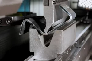
Tooling and Press Brake Setup
The punch radius and V-die opening strongly affect the actual bend radius produced during bending.
A common rule used in sheet metal fabrication:
Actual Bend Radius ≈ V-die opening ÷ 6
Example:
| V-Die Opening | Approx. Radius |
|---|---|
| 24 mm | 4 mm |
| 30 mm | 5 mm |
| 36 mm | 6 mm |
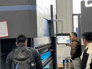
Selecting the proper tooling is essential for achieving the desired bend geometry.Modern CNC press brake machines allow operators to precisely control bending force, angle, and tooling alignment.
Springback in Sheet Metal Bending
Another important factor in sheet metal bending is springback.
After the bending force is removed, the material tends to partially return to its original shape. This effect depends on material strength and elasticity.
Typical springback behavior:
| Material | Springback Level |
|---|---|
| Aluminum | High |
| Stainless Steel | Medium |
| Mild Steel | Low |
Designers often compensate for springback by slightly overbending the part during the press brake process.To compensate for springback, engineers often adjust parameters such as the K factor in sheet metal bending during the design stage.
Practical Sheet Metal Design Tips
To achieve reliable bending results, engineers should follow these best practices:
- Keep the bend radius at least equal to the recommended minimum
- Align bends across the grain direction when possible
- Select proper press brake tooling
- Perform test bends before full production
- Consider springback during design
These practices help ensure consistent bending quality and reduce manufacturing defects.
Common Mistakes in Bend Radius Design
Several design mistakes frequently cause problems in sheet metal fabrication.
1.Using a radius that is too small
This is the most common cause of cracking and material failure.
2.Ignoring grain direction
Bending along the grain increases the risk of fracture.
3.Using incorrect tooling
Incorrect punch or die selection may produce unexpected bend radii.
Conclusion
The minimum bend radius for sheet metal is a critical parameter in both design and manufacturing. Choosing the correct bend radius helps prevent cracking, improves dimensional accuracy, and ensures reliable press brake operation.
By understanding material properties, thickness effects, and tooling influence, engineers can design sheet metal parts that are both functional and manufacturable.
Using a minimum bend radius chart combined with proper engineering guidelines allows manufacturers to achieve consistent bending results across a wide range of materials.
FAQ
What is the minimum bend radius for sheet metal?
The minimum bend radius is the smallest radius that a sheet metal part can be bent without cracking or damaging the material.
What happens if the bend radius is too small?
If the bend radius is smaller than recommended, the outer surface of the metal may crack due to excessive tensile stress.
What is the minimum bend radius for stainless steel?
A common guideline is 1.5 × the material thickness, though the exact value depends on the alloy and bending method.
Does sheet thickness affect bend radius?
Yes. Thicker sheet metal generally requires a larger bend radius to prevent cracking during bending.