Skip to content

press brakes

all elec press brake

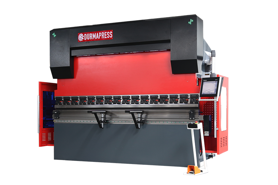
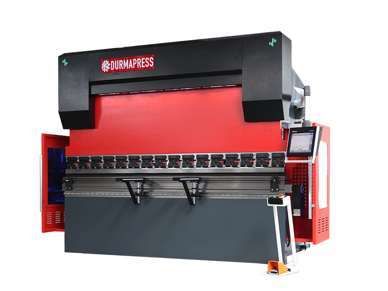
Comparing Electric and Hydraulic Press Brakes: Which Is Right for You?

When discussing press brakes, two types often come into play: the electric press brake and the hydraulic press brake. These machines have distinct differences in principles, performance, and applicable scenarios. It's necessary to carefully consider their characteristics and advantages when choosing the appropriate press brake.

CNC PRESS BRAKE DA58T 4+1 (1)

Inspection and judgment of press brake working accuracy

At present, many companies do not pay attention to the daily management of equipment. Improper use and maintenance of equipment. Or the equipment is used excessively or the operator does not use the equipment according to the equipment operating procedures, resulting in serious loss of equipment accuracy. Some small and medium-sized enterprises will purchase some second-hand equipment, but lack the technology and methods to detect equipment accuracy.

CNC Press Brake TP10S CNC Touch Screen Controller - User Guide

1 Overview.....................................................................................................................................3 1.1 Programming/running............................................................................................................3 1.2 More programming................................................................................................................3 1.3 Advanced parameters............................................................................................................. 4 1.4 Mode selection.......................................................................................................................5 1.5 System parameter...................................................................................................................6 1.6 Machine diagnosis................................................................................................................. 6 2.Debugging system................................................................................................................7 2.1 Valve settings.......................................................................................................................... 7 2.2 Coefficient.............................................................................................................................. 8 2.2.1 X axis....................................................................................................................................8 2.2.2 Y axis................................................................................................................................... 8 2.3 Angle Debugging.................................................................................................................... 9 2.3.1 Upper mold..........................................................................................................................9 2.3.2 Lower mold..........................................................................................................................9 2.3.3 Other parameter.................................................................................................................10 2.4 Angle calibration.................................................................................................................. 10 2.5 Length of calibration.............................................................................................................11 2.6 Frame strength......................................................................................................................12 2.7 Grid ruler.............................................................................................................................. 12 2.8 Mechanical compensation................................................................................................... 13 2.9 Great arc............................................................................................................................... 13 2.10 Y1-Y2 axis.............................................................................................................................14 3.User operation.....................................................................................................................14 3.1 Single… Read More »CNC Press Brake TP10S CNC Touch Screen Controller - User Guide

The pressure of hydraulic press is generally set as the standard pressure when leaving the factory

The pressure of hydraulic press is generally set as the standard pressure when leaving the factory. Customers can adjust the pressure according to the production of different product materials. However, if the pressure output of a press is unstable in the use process, we need to check it to avoid future problems. So what are the reasons for the unstable pressure output of hydraulic press? a) The press spool hole a is blocked, or the diameter of the hole on… Read More »The pressure of hydraulic press is generally set as the standard pressure when leaving the factory

Dazzling S 600 Series - Interactive 2D Graphic Editor for Effortless Workpiece and Tool Data Entry

Dazzling S 600 Series - Interactive 2D Graphic Editor for Effortless Workpiece and Tool Data Entry

Introducing the Dazzling S 600 Series, an interactive 2D graphic editor designed for effortless workpiece and tool data entry. This innovative tool simplifies the process of inputting workpiece and tool information, allowing users to easily create and modify 2D graphics with precision and efficiency. With its user-friendly interface and advanced features, the Dazzling S 600 Series revolutionizes data entry in the manufacturing industry, streamlining workflows and enhancing productivity.

S 600 Series CNC / MOTORS / DRIVES

S 600 range La nuova gamma di CNC Esautomotion nasce dall’esigenza di soddisfare una sempre maggiore richiesta, da parte degli utilizzatori, di CNC performanti,di facile impiego, con estetica e funzionalità al passo con le ultime tendenze. Da ciò la scelta di realizzare una nuova gamma di prodotti per deformazione che ripropongano le eccezionali prestazioni della precedente linea S500 in un ambiente grafico rivisto ed aggiornato e con utilizzo esclusivo di schermi Touch Screen e Multitouch.La nuova linea di Cnc Esa… Read More »S 600 Series CNC / MOTORS / DRIVES

S 600 Series CNC / MOTORS / DRIVES Piega Bending

S 600 range La nuova gamma di CNC Esautomotion nasce dall’esigenza di soddisfare una sempre maggiore richiesta, da parte degli utilizzatori, di CNC performanti, di facile impiego, con estetica e funzionalità al passo con le ultime tendenze. Da ciò la scelta di realizzare una nuova gamma di prodotti per deformazione che ripropongano le eccezionali prestazioni della precedente linea S500 inun ambiente grafico rivisto ed aggiornato e con utilizzo esclusivo di schermi Touch Screen e Multitouch.La nuova linea di Cnc Esa… Read More »S 600 Series CNC / MOTORS / DRIVES Piega Bending

DSP-AP laser safety system

DSP-AP generates a visible laser protection compliant with EN12622 regulation. The beam protects the press brake operator from the danger of being crushed between upper and lower tool. It represents the evolution in press brake safety with respect to the inefficient light curtains or obsolete single-beam protections This device reduces the mute point (speed change point) to up to 4 mm from the sheet metal, thus permitting a remarkable saving in the duration of the bending cycle. As a result,… Read More »DSP-AP laser safety system

CNC Press Brake TP10 CNC Touch Screen Controller - User Guide

Directory 1 Overview.....................................................................................................................................3 1.1 Programming/running............................................................................................................3 1.2 More programming................................................................................................................3 1.3 Advanced parameters............................................................................................................. 4 1.4 Mode selection.......................................................................................................................5 1.5 System parameter...................................................................................................................6 1.6 Machine diagnosis................................................................................................................. 6 2.Debugging system................................................................................................................7 2.1 Valve settings.......................................................................................................................... 7 2.2 Coefficient.............................................................................................................................. 8 2.2.1 X axis....................................................................................................................................8 2.2.2 Y axis................................................................................................................................... 8 2.3 Angle Debugging.................................................................................................................... 9 2.3.1 Upper mold..........................................................................................................................9 2.3.2 Lower mold..........................................................................................................................9 2.3.3 Other parameter.................................................................................................................10 2.4 Angle calibration.................................................................................................................. 10 2.5 Length of calibration.............................................................................................................11 2.6 Frame strength......................................................................................................................12 2.7 Grid ruler.............................................................................................................................. 12 2.8 Mechanical compensation................................................................................................... 13 2.9 Great arc............................................................................................................................... 13 2.10 Y1-Y2 axis.............................................................................................................................14 3.User operation.....................................................................................................................14 3.1… Read More »CNC Press Brake TP10 CNC Touch Screen Controller - User Guide

ru_RURussian
WeCreativez WhatsApp Support
Our customer support team is here to answer your questions. Ask us anything!
👋 Hi, how can I help?